CP-RIO3-04 Rear I/O CP3003-SA
Page C - 6 ID 1052-6929, Rev. 3.0
D R A F T — F O R I N T E R N A L U S E O N L Y
C.5 Module Interfaces
C.5.1 USB Interfaces
There are two identical USB interfaces on the CP-RIO3-04 rear I/O module, each with a max-
imum transfer rate of 480 Mb/s provided for connecting USB devices. One USB peripheral may
be connected to each port. To connect more USB devices than there are available ports, an
external hub is required.
C.5.2 VGA Interface
The 15-pin connector J7 is used to connect a VGA monitor to the CP-RIO3-04 rear I/O module.
Note ...
The USB host interfaces on the CP-RIO3-04 rear I/O module can be used with
maximum 500 mA continuous load current as specified in the Universal Serial
Bus Specification, Revision 2.0. Short-circuit protection is provided. All the sig-
nal lines are EMI-filtered.
Note ...
The rear I/O interface supports the USB 1.1 and USB 2.0 standards. For
USB 2.0 it is strongly recommended to use a cable length not exceeding
3 meters.
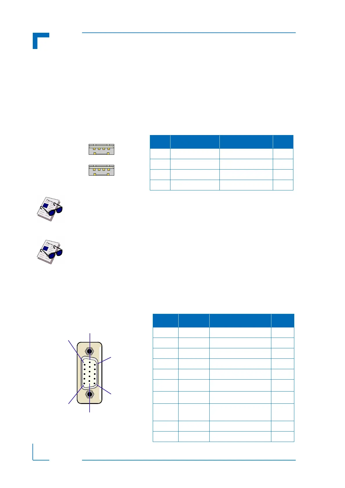
Figure C-4: USB Con. J11/J12
Table C-2: USB Con. J11 and J12 Pinout
PIN SIGNAL DESCRIPTION I/O
1 VCC VCC signal O
2 USB- Differential USB- I/O
3 USB+ Differential USB+ I/O
4 GND GND signal --
Figure C-5: D-Sub VGA Connector J7
Table C-3: D-Sub VGA Connector J7 Pinout
PIN SIGNAL FUNCTION I/O
1 Red Red video signal output O
2 Green Green video signal output O
3 Blue Blue video signal output O
13 Hsync Horizontal sync. TTL Out
14 Vsync Vertical sync. TTL Out
12 Sdata
I
²
C data
I/O
15 Sclk
I
²
C clock
O
9 VCC Power +5V, 140 mA fuse
protection
O
5,6,7,8, 10 GND Ground signal --
4,11 NC -- --