CP3003-SA CP-RIO3-04 Rear I/O
ID 1052-6929, Rev. 3.0 Page C - 9
D R A F T — F O R I N T E R N A L U S E O N L Y
C.5.5 Peripheral Control Interface
A power supply with power management can be connected to the CP-RIO3-04 via the
peripheral control connector J13.
The following figure and table provide pinout information for connector J13.
Figure C-8: Serial Port Connectors
J2 (COMA) and J3 (COMB)
Table C-6: Serial Port Con. J2 (COMA)
and J3 (COMB) Pinout
PIN SIGNAL DESCRIPTION I/O
1 DCD Data carrier detect I
2 DSR Data send request I
3 RXD Receive data I
4 RTS Request to send O
5 TXD Transmit data O
6 CTS Clear to send I
7 DTR Data terminal ready O
8 RI Ring indicator I
9 GND Signal ground --
10 NC Not connected --
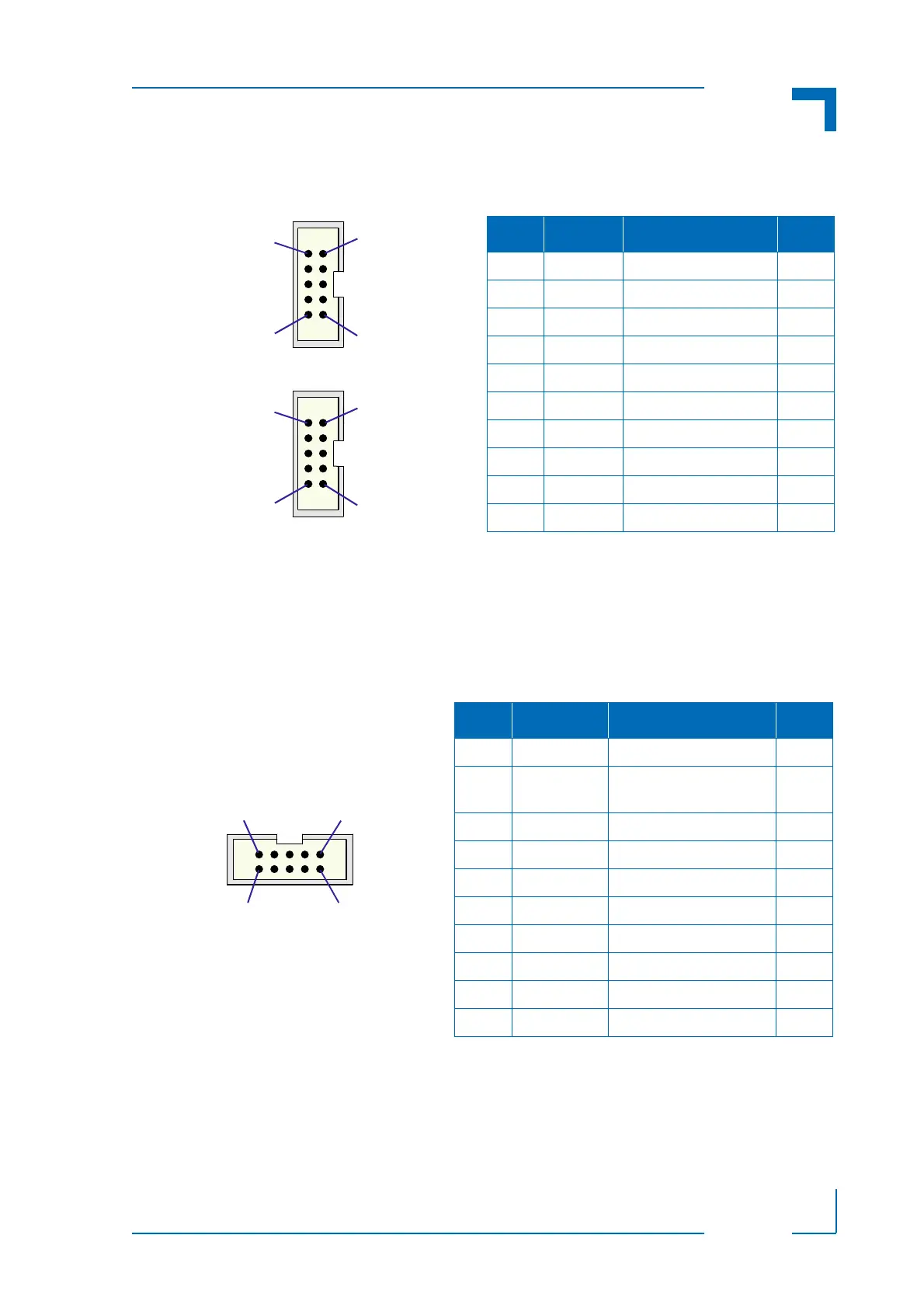
Figure C-9: Peripheral Con. J13
Table C-7: Peripheral Connector J13 Pinout
PIN SIGNAL DESCRIPTION I/O
1 GND Signal ground --
2 PWR_5VSTDBY +5V standby power
(optional)
I
3 RSV Reserved --
4 VCC5V Power +5V O
5 RSV Reserved --
6 VCC3V3 Power +3.3V O
7 PWR_SLPS3# Power supply sleep mode O
8 GND Signal ground --
9 PWR_BTN# Wake-up / sleep input I
10 GND Signal ground --