Functional Description CP3003-SA
Page 2 - 26 ID 1052-6929, Rev. 3.0
D R A F T — F O R I N T E R N A L U S E O N L Y
Ethernet Interfaces
Gigabit Ethernet signals are available either on the front RJ-45 connector or on the rear I/O in-
terface due to the implemented switches on the CP3003-SA. Both Gigabit Ethernet channels
are individually switchable to front or rear I/O. Switching over from front to rear I/O or vice versa
is effected using the uEFI BIOS settings (default: front I/O).
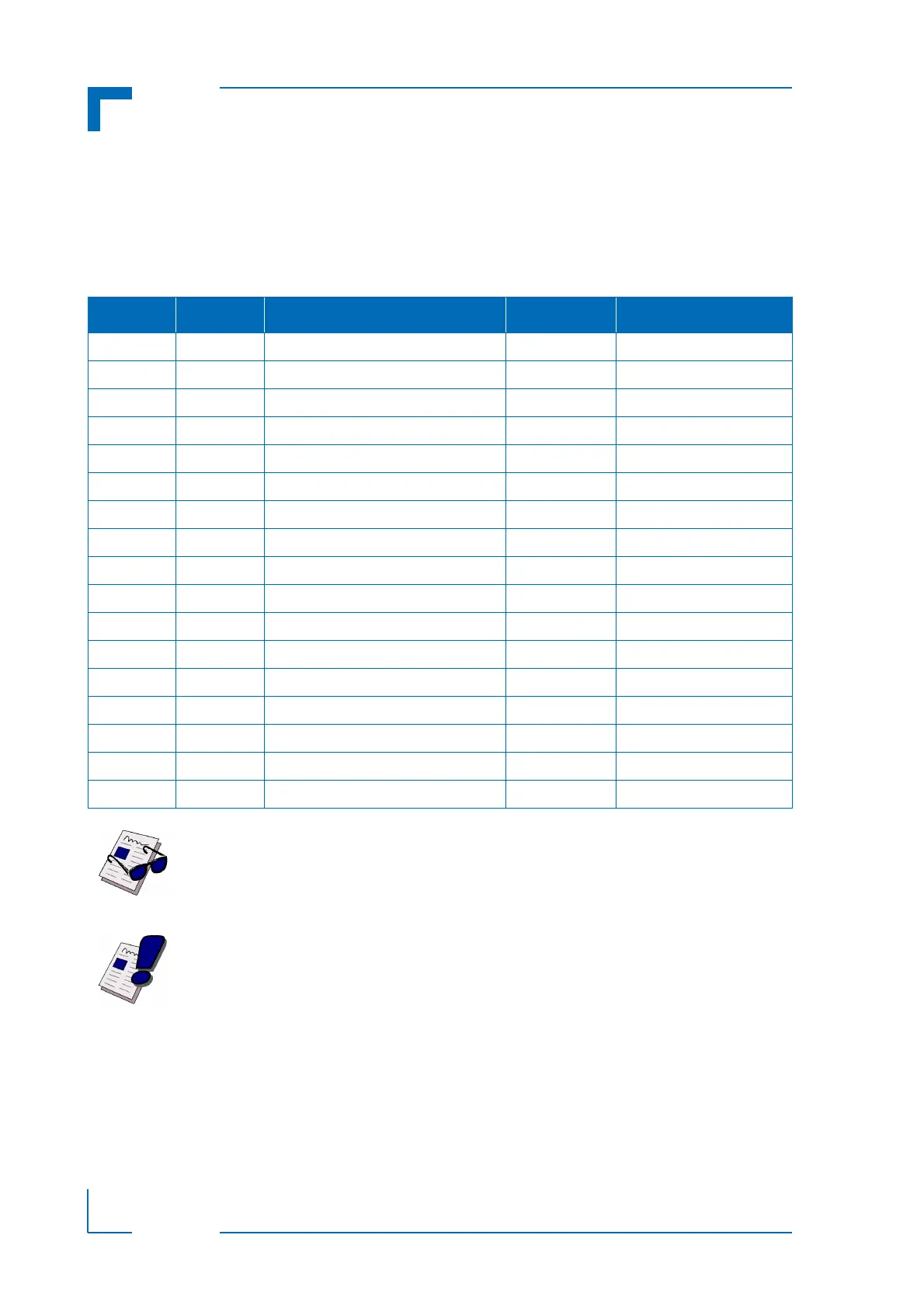
Table 2-21: Gigabit Ethernet Signal Description
PIN on J2 SIGNAL FUNCTION DRIVEN BY SIGNALING VOLTAGE
A14 IPA_DA+ Media-dependent interface port A Bidirectional Analog
B14 IPA_DA- Media-dependent interface port A Bidirectional Analog
A13 IPA_DB+ Media-dependent interface port A Bidirectional Analog
B13 IPA_DB- Media-dependent interface port A Bidirectional Analog
D14 IPA_DC+ Media-dependent interface port A Bidirectional Analog
E14 IPA_DC- Media-dependent interface port A Bidirectional Analog
D13 IPA_DD+ Media-dependent interface port A Bidirectional Analog
E13 IPA_DD- Media-dependent interface port A Bidirectional Analog
A12 IPB_DA+ Media-dependent interface port B Bidirectional Analog
B12 IPB_DA- Media-dependent interface port B Bidirectional Analog
A11 IPB_DB+ Media-dependent interface port B Bidirectional Analog
B11 IPB_DB- Media-dependent interface port B Bidirectional Analog
D12 IPB_DC+ Media-dependent interface port B Bidirectional Analog
E12 IPB_DC- Media-dependent interface port B Bidirectional Analog
D11 IPB_DD+ Media-dependent interface port B Bidirectional Analog
E11 IPB_DD- Media-dependent interface port B Bidirectional Analog
C12 RIO_1V9 Power supply for magnetics center tap CP3003-SA 1.9V
Note ...
The Ethernet magnetics must be placed on the rear I/O module. The Ethernet
magnetics center tap must be connected to the dedicated 1.9 V power supply
provided by the CP3003-SA (pin C12 on J2).
Warning!
Pin C12 is a power supply OUTPUT. This pin MUST NOT be connected to any
other power source, either within the backplane itself or within a rear I/O mod-
ule.
Failure to comply with the above will result in damage to your board.