CP3003-SA Configuration
ID 1052-6929, Rev. 3.0 Page 4 - 3
D R A F T — F O R I N T E R N A L U S E O N L Y
4. Configuration
4.1 DIP Switch Configuration
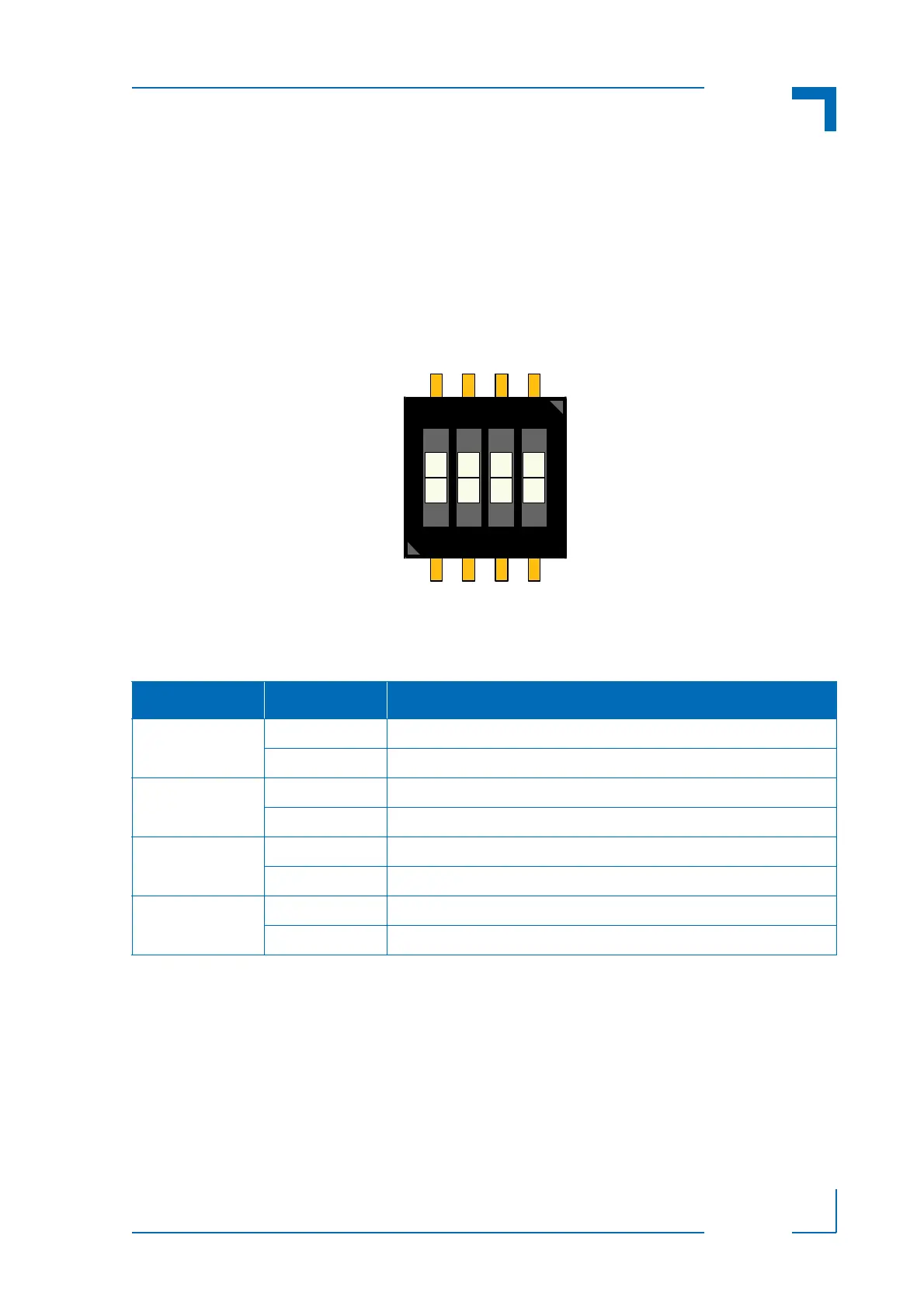
The DIP switch consists of four switches for board configuration: switch 1 for POST code indica-
tion on LED0..3, switch 2 for the SPI boot flash selection, switch 3 for reset configuration, and
switch 4 for the uEFI BIOS configuration.
Figure 4-1: DIP Switch SW1
The following table indicates the functionality of the four switches integrated in the DIP switch.
The default setting is indicated by using italic bold.
To clear the uEFI BIOS settings and the passwords, proceed as follows:
1. Set DIP switch SW1, switch 4, to the ON position.
2. Apply power to the system.
3. Wait 30 seconds and then remove power from the system. During this time period no
messages are displayed.
4. Set DIP switch SW1, switch 4, to the OFF position.
Table 4-1: DIP Switch SW1 Functionality
SWITCH SETTING FUNCTIONALITY
1 OFF Boot-up with POST code indication on LED0..3
ON Boot-up with no POST code indication on LED0..3
2 OFF Boot from the standard SPI boot flash
ON Boot from the recovery SPI boot flash
3 OFF Edge-sensitive reset configuration (QM77 reset implementation)
ON Level-sensitive reset configuration (FPGA PGOOD logic to QM77)
4 OFF Boot using the currently saved uEFI BIOS settings
ON Clear the uEFI BIOS settings and use the default values