CP3003-SA Functional Description
ID 1052-6929, Rev. 3.0 Page 2 - 13
D R A F T — F O R I N T E R N A L U S E O N L Y
2.11.6 Gigabit Ethernet
The CP3003-SA board includes three 10Base-T/100Base-TX/1000Base-T Ethernet ports based
on three Intel® 82574L Gigabit Ethernet controllers, which are connected to the x1 PCI Express
interfaces of the Intel® QM77 Express Chipset. Two Gigabit Ethernet interfaces are switchable
between front I/O and rear I/O. The third Gigabit Ethernet interface is available on the CP3003-
HDD extension module (8 HP).
The Intel® 82574L Gigabit Ethernet Controller’s architecture is optimized to deliver high per-
formance with the lowest power consumption. The controller's architecture includes indepen-
dent transmit and receive queues and a PCI Express interface that maximizes the use of bursts
for efficient bus usage.
The Boot-from-LAN is supported on all three Ethernet interfaces. Wake-on-LAN is supported
on the two Ethernet interfaces that are switchable between front I/O and rear I/O. After an op-
erating system shutdown, a 1000Base-T Gigabit connection is automatically reduced to 100
Mbit or 10 Mbit operation and the Ethernet controller waits to receive a broadcast or unicast
packet with an explicit data pattern to assert a signal or a PME message to wake up the system.
If the main power is switched off after an OS shutdown, a 5V standby supply must be provided
over the J2 rear I/O CompactPCI connector to continue powering the Wake-on-LAN relevant
devices.
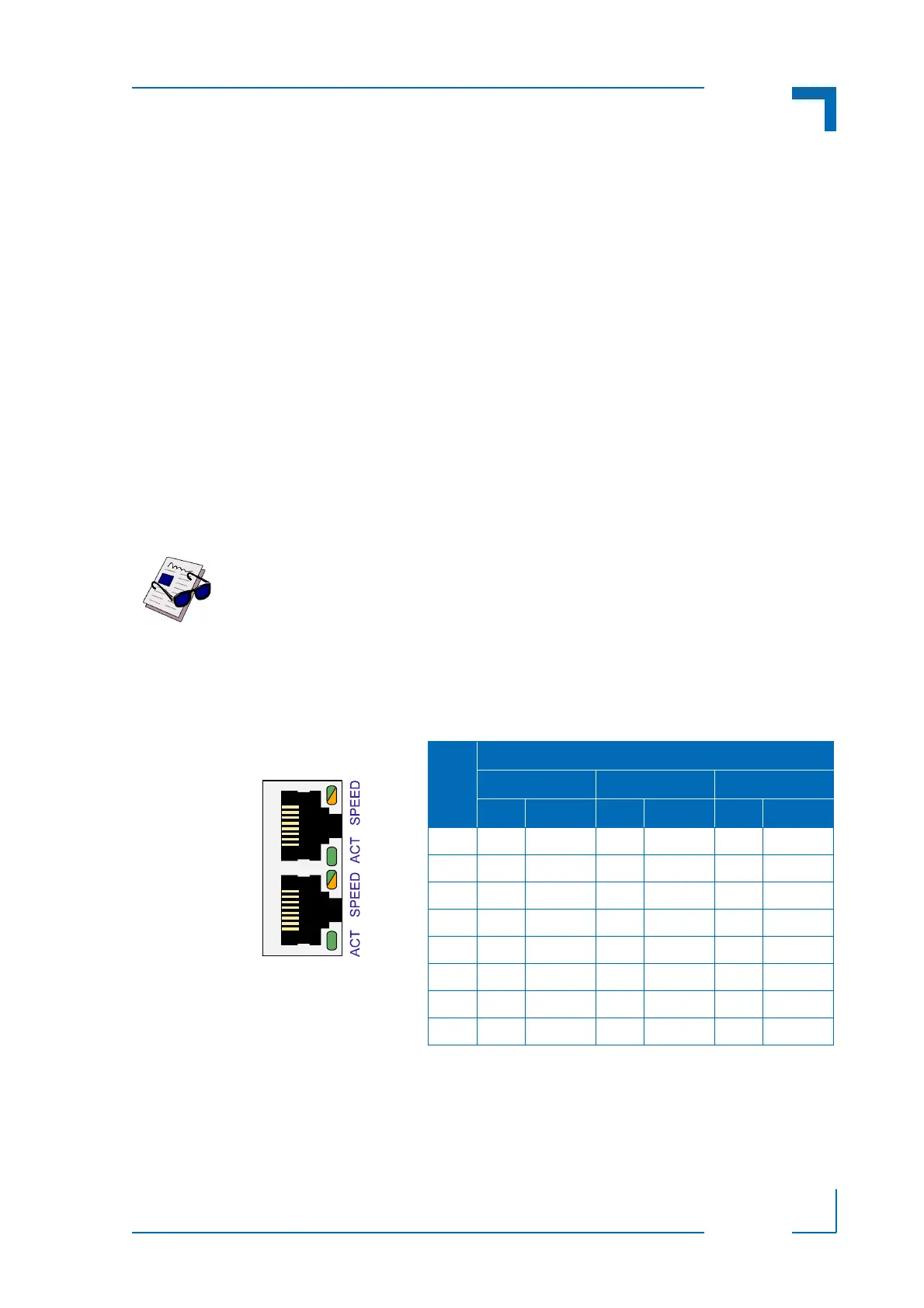
The dual Gigabit Ethernet connector J7A/B is comprised of two RJ-45 connectors with integrat-
ed magnetics and supplies the 10Base-T, 100Base-TX and 1000Base-T interfaces to the
Ethernet controller.
Ethernet LED Status
ACT (green): This LED monitors network connection and activity. The LED lights up when a
valid link (cable connection) has been established. The LED goes temporarily off if network
packets are being sent or received through the RJ-45 port. When this LED remains off, a valid
link has not been established due to a missing or a faulty cable connection.
Note ...
The Ethernet transmission can operate effectively using a CAT5 cable with a
maximum length of 100 m.
Figure 2-3: Dual Gigabit Ethernet
Connector J7A/B
Table 2-10: Pinout of Dual GbE Con. J7A/B
PIN
MDI / STANDARD ETHERNET CABLE
10BASE-T 100BASE-TX 1000BASE-T
I/O SIGNAL I/O SIGNAL I/O SIGNAL
1 O TX+ O TX+ I/O BI_DA+
2 O TX- O TX- I/O BI_DA-
3 I RX+ I RX+ I/O BI_DB+
4----I/OBI_DC+
5----I/OBI_DC-
6 I RX- I RX- I/O BI_DB-
7----I/OBI_DD+
8----I/OBI_DD-