1775 IMU Technical Manual
9
Interface Cable
Interface Cable
The power and data interface cable must be fitted with a 15-socket
(female) Micro-D connector per MIL-DTL-83513 with a Flourosilicone
interfacial seal. You can purchase a 24" (60 cm) shielded interface cable
with this connector from KVH (KVH part no. 32-1293-02).
If your application requires a serial cable or interface adapter (such as
an RS422-USB serial adapter), make sure it is compatible with the IMU
and supports speeds of at least 4 Mbps baud (KVH recommends USB
converter Startech ICUSB422 or equivalent set at RS-422, no echo, no
term). Also be sure to use shielded cables to prevent signal loss and
noise interference.
Data Communications Equipment
A computer or other data communications device is necessary to
communicate with the IMU. This equipment's serial port
communications must match the IMU’s serial port settings for proper
operation.
When connected to the IMU, you can enter commands directly from
the terminal or through a terminal emulation application.
Use RS-422 differential signaling methods for all 1775 IMU digital
control signals (KVH preferred). Alternatively, RS-422 single-ended
signaling may be used if cabling susceptibility and other
environmental interferences are proven acceptable. For more
information, refer to “Appendix C: Electrical Signaling ICD” on
page 31.
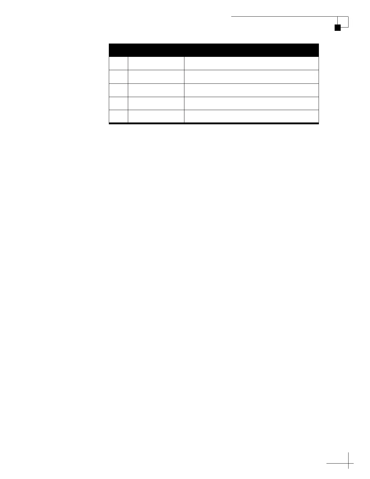
11 MSync (+) Master Sync High (External Clock) (Optional)
12 TOV-Out (+) Time of Validity Signal High (Optional)
13 Config-RST-In (+) IMU Configuration Reset High (Optional)
14 EXT-RST (+) IMU Reset High (Optional)
15 Signal-GND Do Not Connect
Pin Type Description

 Loading...