1775 IMU Technical Manual
22
Mounting the IMU
Mounting the IMU
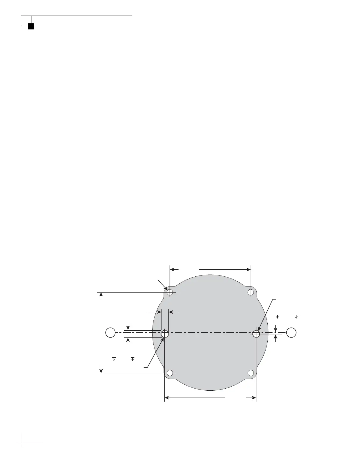
The 1775 IMU is easily mounted to a structure using the four 0.173"
(4.39 mm) mounting holes on the base of the enclosure (see
Figure 21). An alignment hole 0.198" (5.03 mm) and an alignment
slot 0.218" x 0.198" (5.54 mm x 5.03 mm) are provided at the middle
edge of the enclosure for alignment purposes. They are designed for
5.004-5.012 mm dowel pins with 0.1" (2.5 mm) protrusion.
NOTE: To ensure precise alignment, rotate the IMU clockwise before
tightening the mounting screws.
The IMU base material is aluminum with a clear chromate finish per
MIL-DTL-5541, class 3. To ensure optimal heat transfer (conductive
cooling) and electrical grounding through the chassis, mount the IMU
base to a clean, flat, unpainted metal surface.
Also be sure to orient the IMU with the desired measurement axes. As
an alternative, you may configure a rotation matrix to set the output
axes relative to the physical orientation of the measurement axes (see
“Configuration Options” on page 14).
NOTE: All dimensions are shown in inches [millimeters] format.
Figure 21: Mounting Holes (Bottom View)
Bottom View
Alignment Hole
Ø0.1980 ±0.0005
[Ø5.029 ±0.013]
Mounting Hole
4x Ø0.173 [4.39]
0.218
[5.54]
0.1980 ±0.0005
[5.029 ±0.013]
2.432
[61.77]
2.750
[69.85]
2.432
[61.77]
Alignment Slot
C
L
C
L
0.04
[1.02]
0.110 [ 2.8]
0.110 [ 2.8]

 Loading...