This document contains proprietary information of KVH Industries, Inc. and neither this document nor said proprietary information shall be
published, reproduced, copied, disclosed, or used for any purpose without the express written permission of a duly authorized KVH representative.
Page 7 of 77
3 System Overview
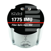
The 1775 IMU is a compact, commercial strap-down inertial sensor system using KVH's
advanced Fiber Optic Gyros combined with low-noise MEMS accelerometers and
magnetometers. It is intended for use in precision guidance and stabilization applications
where high bandwidth, low noise, and bias stability performance levels are important. The
1775 IMU is lightweight, low power, and rugged, offering accurate performance in extreme
environments. Its flexible digital data and power interface is designed for ease of integration in
new applications and upgrades to existing systems. It is part of a family of commercial IMUs,
which includes the 1725 and 1750 IMUs, which offer the same physical package, but different
price and performance specifications.
3.1 Functional Overview
The 1775 IMU is a nine-Degree of Freedom (9-DOF) inertial sensor package containing three
accelerometers, three gyroscopes, a 3-D magnetometer, and internal temperature sensors. All
sensors are directly fixed to the housing frame.
Internally, three single-axis interferometric Fiber Optic Gyros (FOGs) are used to measure the
angular rate at three orthogonal axes. The 1775 IMU uses three single-axis MEMS
accelerometers to measure linear Acceleration along these orthogonal axes. A temperature
compensated, three-axis integrated circuit (IC) magnetometer provides low field (< 10 Gauss)
magnetic sensing and compensation of magnetic disturbances.
The 1775 IMU provides a full-duplex, asynchronous, RS-422 level serial interface for signal
communications to an external control system(s). The serial communications interface
transmits sensor and status data from the IMU and receives commands and data from the
user. Serial baud is configurable and is stored in non-volatile/persistent memory. The digital
control signals and status use RS-422 differential signaling. Digital control signal pairs are
External Reset (In), Time of Validity (Out), Master Synchronization Clock (In), and
Configuration Software Reset (In).
The 1775 IMU electronics offers user options for changing its run-time configuration, such as
operating services (e.g., filters, serial communications, and other characteristics as described
in this document).

 Loading...