This document contains proprietary information of KVH Industries, Inc. and neither this document nor said proprietary information shall be
published, reproduced, copied, disclosed, or used for any purpose without the express written permission of a duly authorized KVH representative.
Page 65 of 77
12 Data Output Signal-Processing
During Normal Mode, operation the IMU Controller Board (ICB) needs to process data from
its sensor sub-systems and prepare it for output to the user system. The ICB is continually
sampling its various sensor data sub-systems and is checking for user requests for data and
commands. It does this through a variety of interrupt-driven DMA (direct memory access) and
polled signals. A simplified diagram of the primary processes related to the gyro and
accelerometer signal-processing is shown in Figure 12-1.
12.1 Signal-Processing Diagram and Key
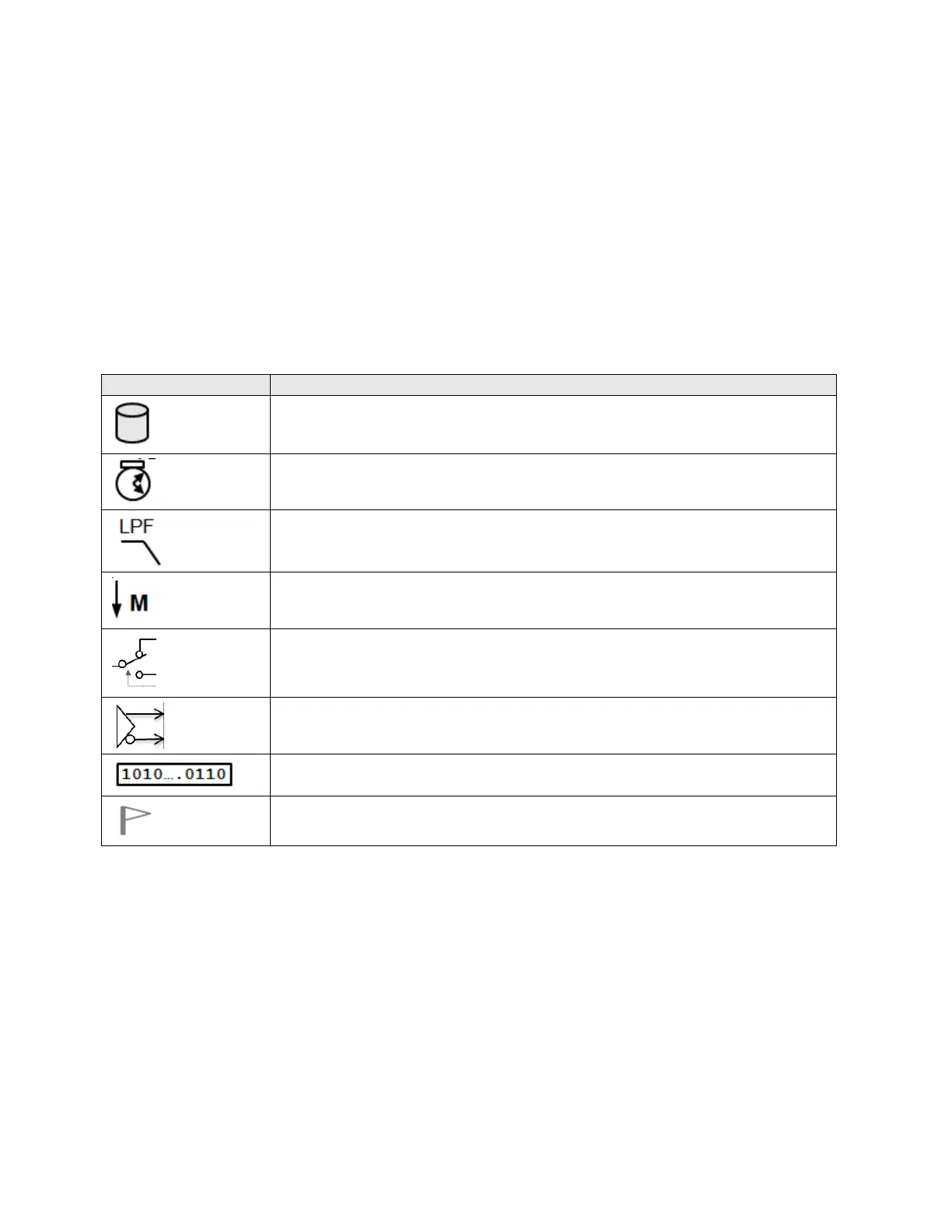
Table 12-1 describes some of the symbols used in the diagram.
Table 12-1: Signal-Processing Symbols
Data container; memory storage of data together with meta-data such
as timestamps
Indicates a timestamp process. The ICB uses an internal clock with
better than 20ns resolution to track relative times of various events
Indicates a low-pass filter process
Indicates the downsampling portion of sample rate reduction by a factor
of M; (M is an industry standard operator symbol for deciMation)
Indicates a switchable data path;, possibly a virtual switch as in a
software path rather than a physical switch
Indicates a differential signal output
Indicates serial data stream
Indicates a semaphore flag for inter-process communications

 Loading...