This document contains proprietary information of KVH Industries, Inc. and neither this document nor said proprietary information shall be
published, reproduced, copied, disclosed, or used for any purpose without the express written permission of a duly authorized KVH
representative.
10.3 MSYNC (Master Synchronization) Input
By default, the 1775 IMU will internally self-time the output message rate according to the
configuration of the =DR command.
The 1775 IMU provides an optional RS-422 differential input (named MSYNC+/MSYNC-) that
allows the user to request data output within the limits of the unit. When configured for external
MSYNC mode, asserting a positive RS-422 compliant voltage from the MSYNC+ pin to the
MSYNC- pin will result in the unit sending out a data message in the configured format. These
pins may be left disconnected at the unit interface connector unless external MSYNC is
desired. The configuration of the internal or external data output requests is controlled by the
=MSYNC command.
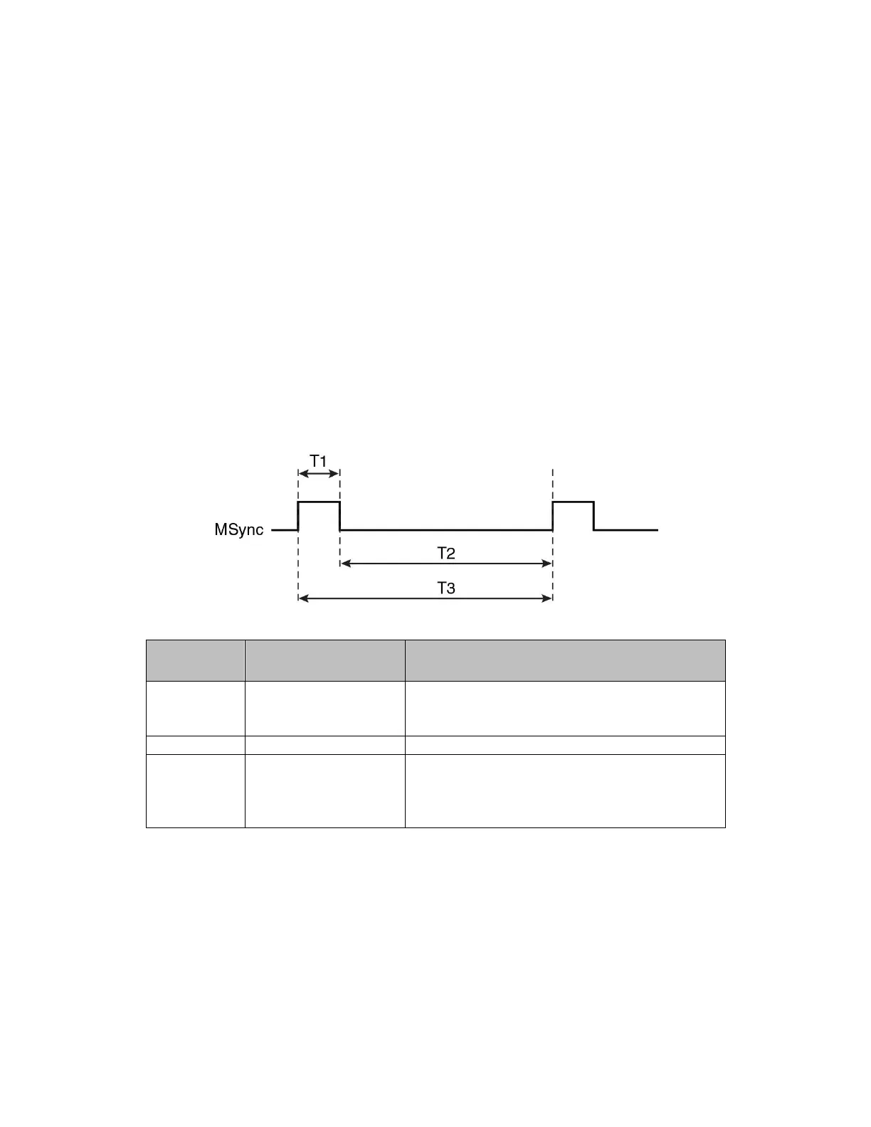
Internal to the IMU, the MSYNC signal, whether internally or externally generated, will be
captured and will cause the IMU to sample its sensor data and prepare and transmit a data
message (see Figure 10-1). MSYNC is shown in the diagram as a single signal and assumes
that MSYNC+ and MSYNC- operate together as a differential pair to define the active (high) or
deasserted (low) state.
Figure 10-1: MSYNC Signals
Table 10-1: MSYNC Timing Parameters
MSYNC+ high and MSYNC- low
≥30 µs; Recommended high time is less
than approximately 90 µs.
MSYNC+ low and MSYNC- high ≥30 µs
Period between
rising edges
0.2-2000 ms; Note: MSYNC might be sent
faster than 200us when using the BIT
function, but in no cases should it be sent
faster than 100us or it may be ignored.

 Loading...