This document contains proprietary information of KVH Industries, Inc. and neither this document nor said proprietary information shall be
published, reproduced, copied, disclosed, or used for any purpose without the express written permission of a duly authorized KVH representative.
Page 19 of 77
5.3 Built-In Test and Extended Built-In Test
During normal operation, if the user wants the unit to perform a BIT, they must request it using
the “?bit” command or the extended “?bit,2” command, described in Section 8. The output of a
BIT is described in Table 5-11. The user-requested ?bit results are performed without affecting
real-time operations or high-speed message output. The user-requested ?bit,2 results contain
extended test diagnostics information and may impact high-speed message outputs during the
extended BIT communication time.
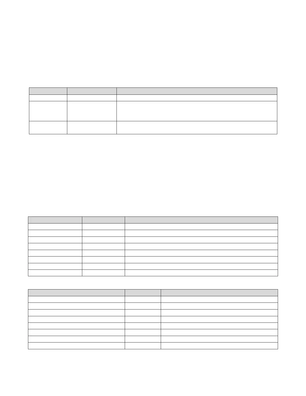
Table 5-11: Normal Mode BIT Output
Always 0xFE8100AA or 0xFE8100AB (transmitted 0xFE first)
The data is described in Table 5-12 through Table 5-19.
Is 6 bytes for ?bit (header 0xFE8100AA)
Is 8 bytes for ?bit,2 (header 0xFE8100AB)
The checksum will be calculated by accumulating the sum of
each byte of data, modulo 256.
The results of each test are indicated with a 1-bit pass/fail flag, 1 indicating a “pass” condition,
while a 0 indicates reduced confidence in the measurement (“fail”). (See Table 5-12 through
Table 5-19 for the complete test list.) Most users do not need the granularity provided by these
six bytes, but the extra data is useful for diagnostic purposes. (See Table 5-21 for which bits
are relevant for each sensor.)
In the following tables (Table 5-12 through Table 5-19), the reserved bits are the most
significant bits of their respective bytes. Byte 0 is the first transmitted, byte 7 is the last. The
number in parentheses in the “Bit Number” column is the number referenced by Table 5-20.
Table 5-12: Test Results Byte 0
Notes (Unless Otherwise Noted: 1 = PASS, 0 = FAIL)
Table 5-13: Test Results Byte 1

 Loading...