1775 IMU Technical Manual
8
Interface Connector
Interface Connector
The 1775 IMU is equipped with a 15-pin (male) Micro-D interface
connector of the following type: MIL-DTL-83513. Figure 6 shows the
connector location. Figure 7 describes the function of each pin. For
more information, refer to “Appendix C: Electrical Signaling ICD” on
page 31.
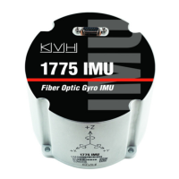
Figure 6: Interface Connector Location
Figure 7: Interface Connector Pins
Pin Type Description
1 RS422-TX (+) IMU RS422 Transmit High
2 RS422-TX (–) IMU RS422 Transmit Low
3 RS422-RX (–) IMU RS422 Receive Low
4 RS422-RX (+) IMU RS422 Receive High
5 EXT-RST (–) IMU Reset Low (Optional)
6 Config-RST-In (–) IMU Configuration Reset Low (Optional)
7 MSync (–) Master Sync Low (External Clock) (Optional)
8 TOV-Out (–) Time of Validity Signal Low (Optional)
9 Power (–) Power Return
10 Power (+) 9-36 VDC Power
Interface Connector
Pin 1

 Loading...