1775 IMU Technical Manual
7
Output Orientation
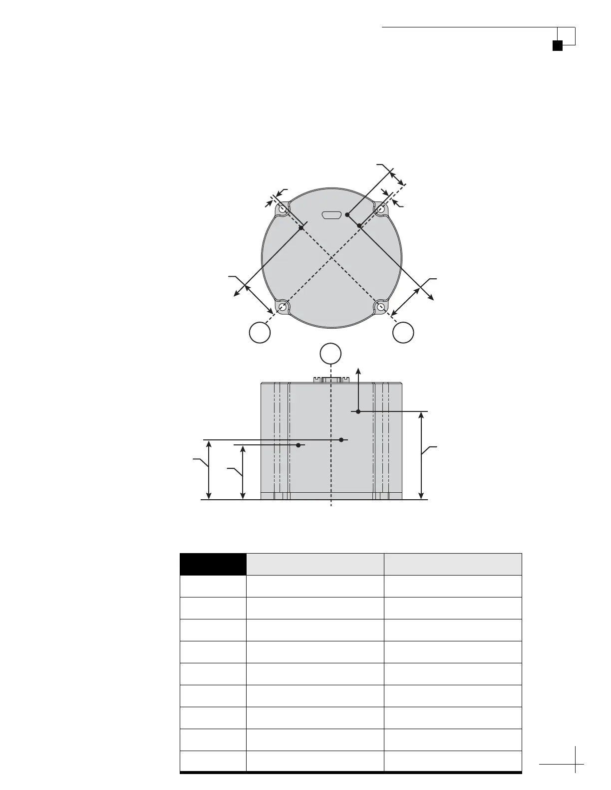
Figure 4 below shows the general physical location of the
accelerometer axes and the location of the sensing point on each axis.
Figure 5 describes the specific location of the accelerometer axes in
Figure 4 for each 1775 IMU variant.
Figure 4: Accelerometer Axes and Sensing Points
NOTE: All dimensions are shown in inches (millimeters) format.
Figure 5: Location of Accelerometer Proof Mass Coordinates
Coordinate KVH Part No. 01-0363-01 KVH Part No. 01-0363-25
Xx 0.02 (0.5) -0.04 (-1.0)
Xy -1.03 (-26.2) -1.03 (-26.2)
Xz 1.32 (33.5) 1.32 (33.5)
Yx -1.01 (-25.6) -1.01 (-25.6)
Yy -0.46 (-11.7) -0.51 (-13.0)
Yz 1.46 (37.1) 1.46 (37.1)
Zx -1.01 (-25.7) -1.01 (-25.7)
Zy -0.02 (-0.5) -0.02 (-0.5)
Zz 1.77 (45.0) 1.77 (45.0)
Top View
Yx and Zx
Xy
C
L
C
L
+X Axis
Yy
Zy
+Y Axis
Z
Y
Side View
+Z Axis
Zz
Xz
Yz
C
L
Z
X
Y
X
Xx

 Loading...