This document contains proprietary information of KVH Industries, Inc. and neither this document nor said proprietary information shall be
published, reproduced, copied, disclosed, or used for any purpose without the express written permission of a duly authorized KVH
representative.
3.2 Electrical Interface Overview
The 1775 IMU uses a MIL-DTL-83513 Micro-D interface connector located on the top face of
the housing. For more information, refer to the Interface Control Drawing (KVH Drawing 99-
0353) part of which is copied below, for easy reference (see Figure 3-1). Figure 3-2 below
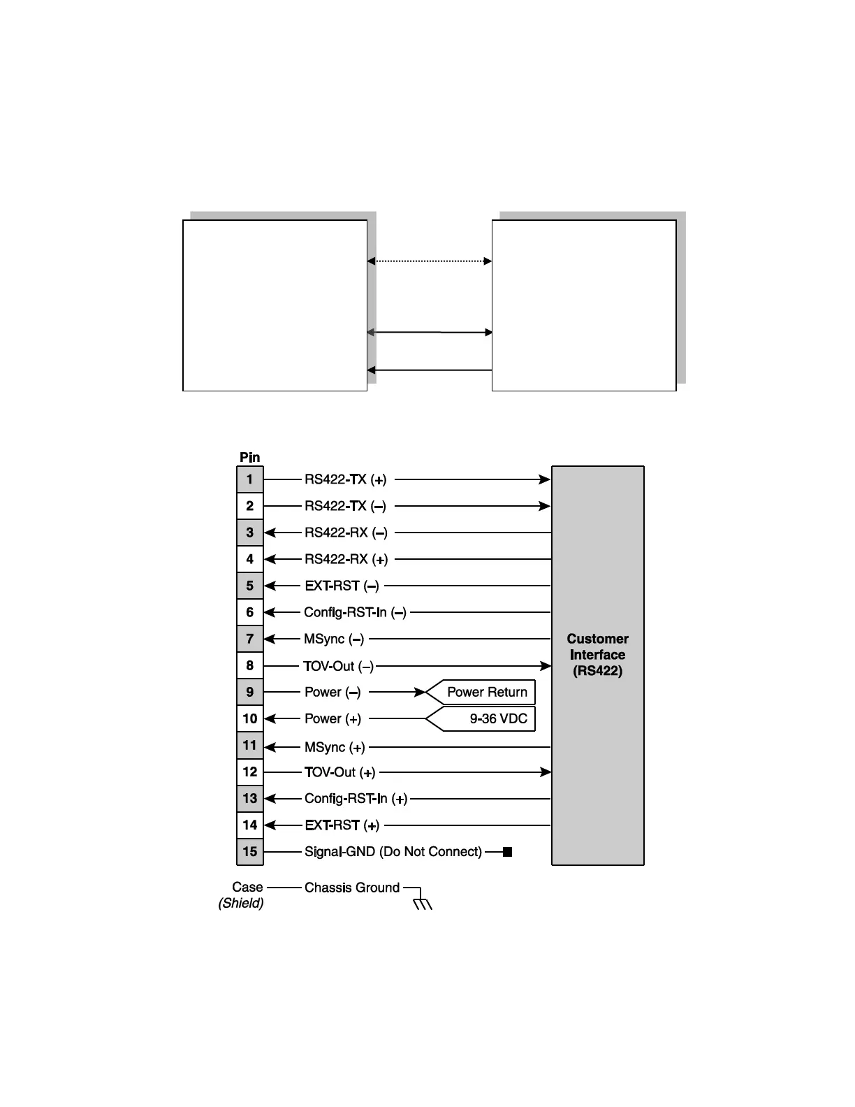
shows the signals and associated pin numbers.
Figure 3-1: 1775 IMU Interface Block Diagram
Figure 3-2: 1775 IMU Wiring Diagram
Control System
(Customer
Furnished)
1775 IMU

 Loading...