This document contains proprietary information of KVH Industries, Inc. and neither this document nor said proprietary information shall be
published, reproduced, copied, disclosed, or used for any purpose without the express written permission of a duly authorized KVH
representative.
The output data is aligned to an end-user configurable axis of orientation. By default, axes X
The
user
, Y
The user
and Z
The user
are equal to X
Sensor
, Y
Sensor,
and Z
Sensor
, respectively. The BIT status,
however, is always indicated relative to the physical sensors inside the device (axes X
Sensor
,
Y
Sensor,
and Z
Sensor
). The end-user is responsible for determining what course of action should
be taken if one or more of the input axes fail. (See Section 9 for a description of the input axes
and see Section 8.1 for details about the =AXES command needed to change the alignment of
the axes as desired.)
5.2.1 Sample Output
An example data output string of Format A follows. In this example, all sensor outputs are
assumed to be valid. Spaces are shown for ease of reading and the ASCII text values
displayed would be replaced with the hexadecimal values they represent. (See Table 5-10 for
a detailed description of the string.)
FE 81 FF 55 37 A9 6A 6E 38 58 6C 1F B7 5B F8 62 BF 80 3E 78 BB 65 0D 28 3B 0A 37 AC
77 3D 00 28 4B FA 34 D8
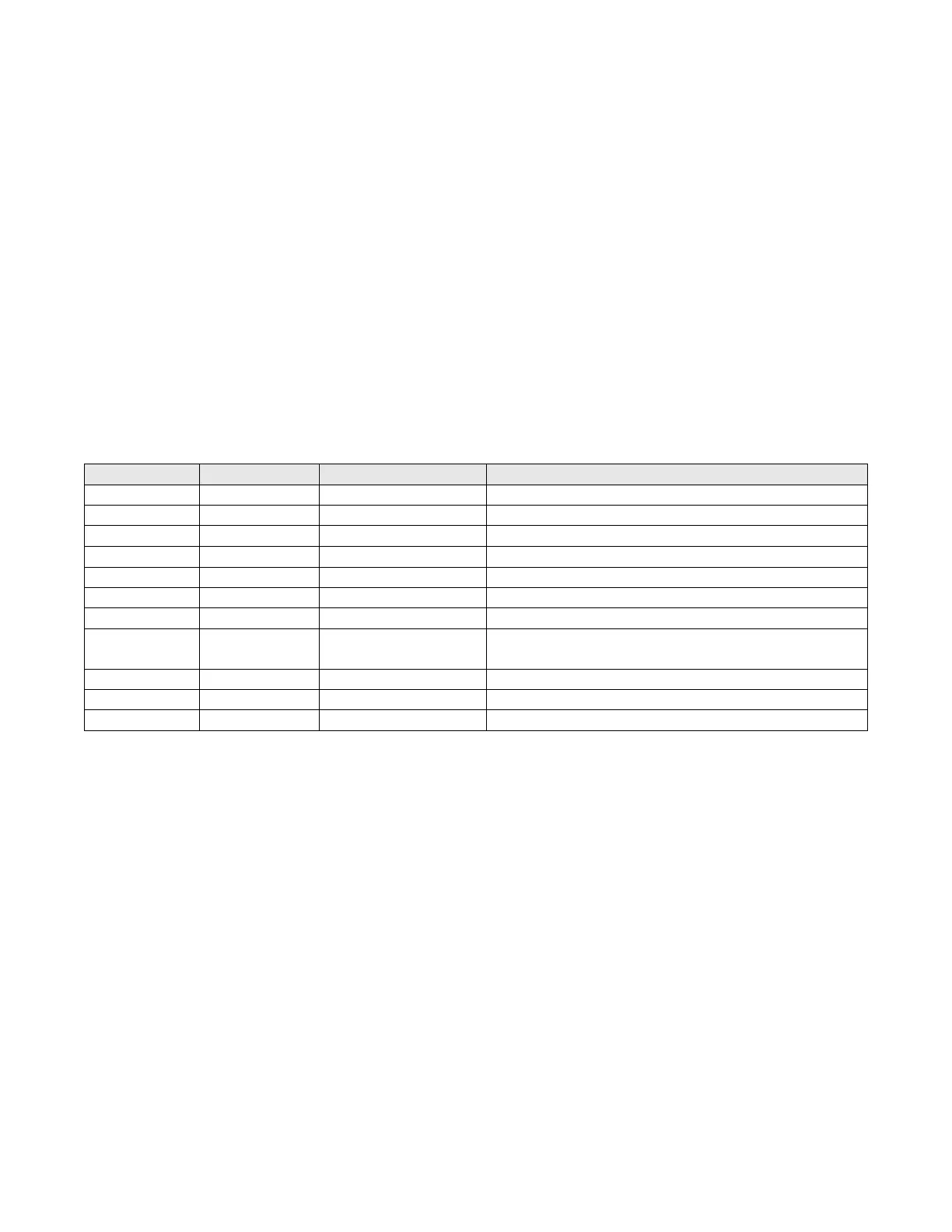
Table 5-10: Breakdown of Sample Output
Configuration dependent (default: delta radians)
Configuration dependent (default: delta radians)
Configuration dependent (default: delta radians)
Configuration dependent (default: ºC)

 Loading...