1775 IMU Technical Manual
25
Troubleshooting
Continuous BIT Status Information
As detailed in the message structure data table example on page 12,
byte 24 (message format A) or 28 (message format B and C; refer to
“Appendix C: Electrical Signaling ICD” on page 31 for more
information) of the IMU’s output message (excluding the message
header) reports the general status of the gyros and accelerometers.
Converted to hexadecimal, a “77” status byte indicates normal status.
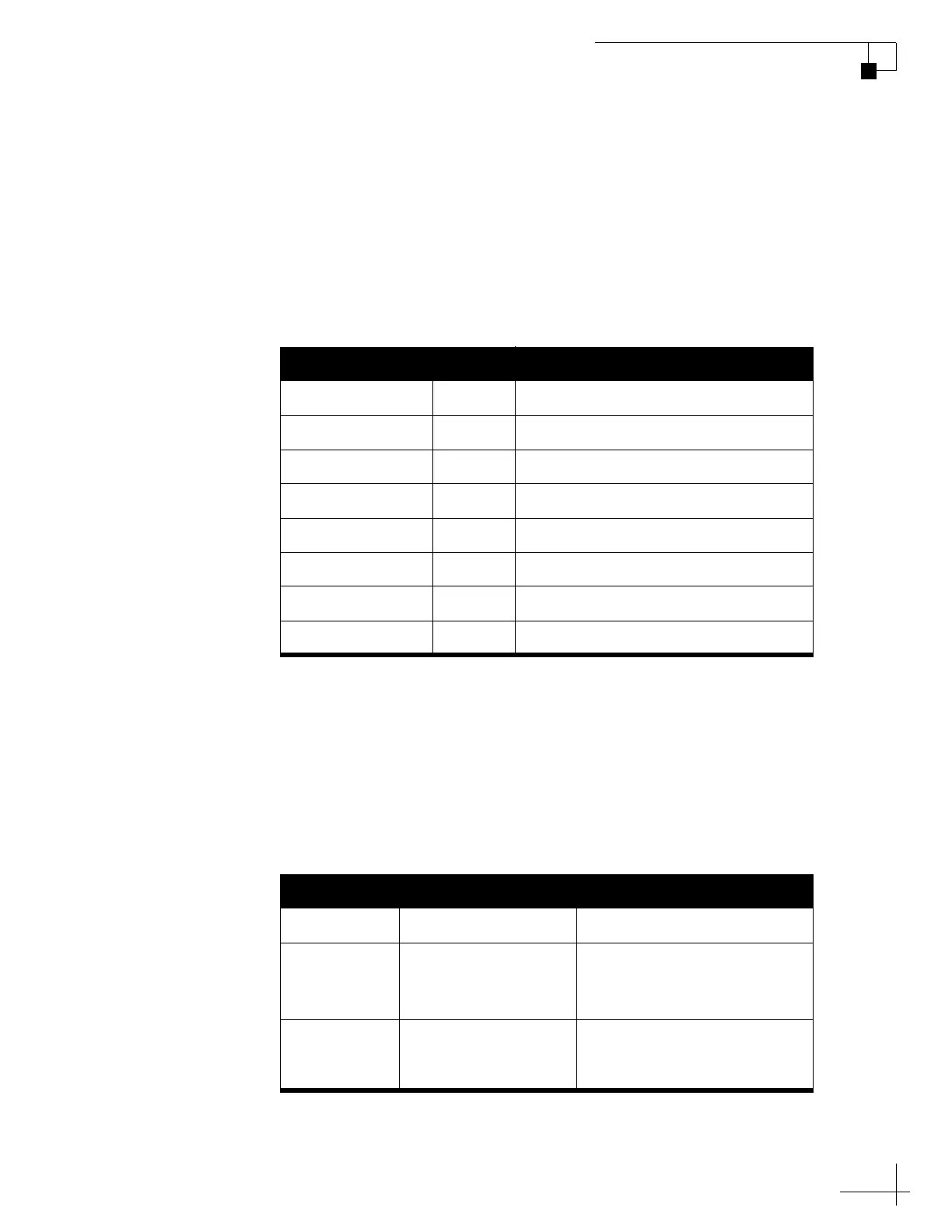
Figure 24: Status Byte Format
Extended BIT Status Information
When the IMU is first powered on, and upon user request, the IMU
outputs an extended BIT message consisting of six or eight bytes of
detailed status information for diagnostics. Converted to hexadecimal,
the following message indicates normal status:
“FE 81 00 AA 7F 7F 7F 7F 7F 7F 23”.
Figure 25: Extended BIT Message Format
Datum Bit # Notes
Gyro X 0 (LSB) 1 = Valid data, 0 = Invalid data
Gyro Y 1 1 = Valid data, 0 = Invalid data
Gyro Z 2 1 = Valid data, 0 = Invalid data
Reserved 3 Always 0
Accelerometer X 4 1 = Valid data, 0 = Invalid data
Accelerometer Y 5 1 = Valid data, 0 = Invalid data
Accelerometer Z 6 1 = Valid data, 0 = Invalid data
Reserved 7 Always 0
Function Total # Bytes Description
Header 4 0xFE8100AA
Message data 6
Refer to “Appendix C:
Electrical Signaling ICD” on
page 31.
Checksum 1 Calculated by accumulating
the sum of each byte of data,
modulo 256

 Loading...