This document contains proprietary information of KVH Industries, Inc. and neither this document nor said proprietary information shall be
published, reproduced, copied, disclosed, or used for any purpose without the express written permission of a duly authorized KVH representative.
Page 29 of 77
However, the reference frame does not to need to be rotated to a specific position. The angles
specified in the rotation matrices below are from the sensor axis to the desired user axis. The
sign of the angle is consistent with the angle of rotation, positive (counterclockwise) and
negative (clockwise) as viewable from positive infinite (see Figure 9-1).
)cos()s in(0
)sin()cos(0
001
)(
x
R
)cos(0)sin(
010
)sin(0)cos(
)(
y
R
100
0)cos()s in(
0)sin()cos(
)(
z
R
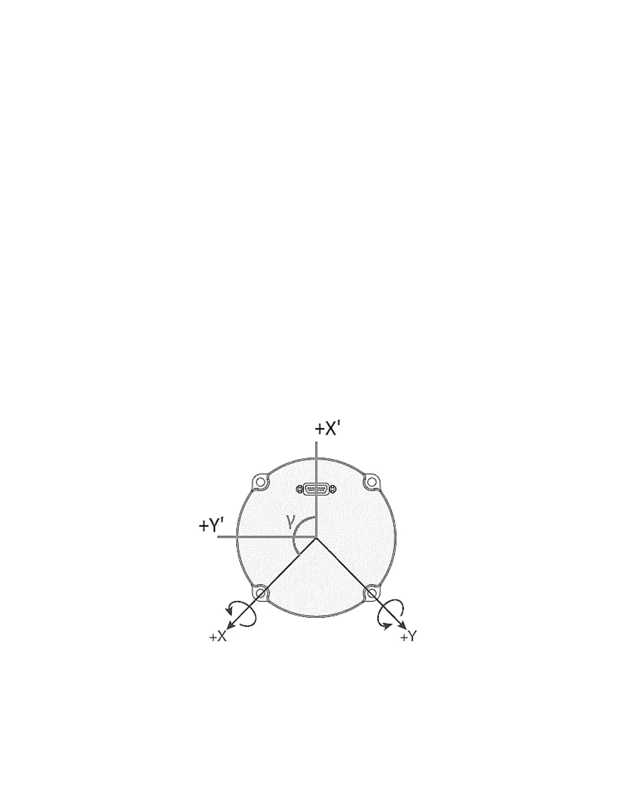
Example: to configure the IMU to use the user axes X’ and Y’ in the figure below, instead of the
sensor axes at the default locations of +X and +Y, use the R
z
rotation matrix. The value of γ will
be -135 degrees.
Example (the default axes alignment):
=AXES,1.0,0.0,0.0,0.0,1.0,0.0,0.0,0.0,1.0

 Loading...