44
6 Commissioning
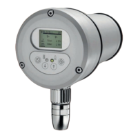
3. Press to display the switch-on parameters and the process reliability.
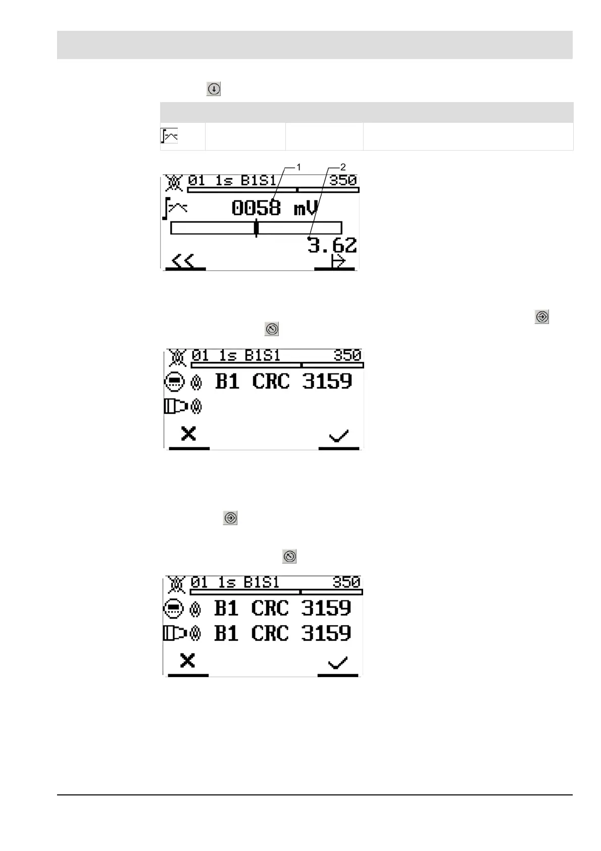
4. To send the data from the level of the operating unit to the flame scanner, press .
Alternatively, press to reject it.
5. Compare the data sent to the flame scanner with the data at the level of the operating unit.
Then:
a) Press within 8 seconds to save the data. A countdown of 8 seconds begins. This
is accompanied by flashing. During this countdown, you have to confirm the setting by
pressing ENTER. If you do not, an error message appears and the setting is rejected.
b) Alternatively, press to reject the data.
Icon Name Value Explanation
Switch-on level 0 ... 2,500 mV Trigger threshold "flame ON"
Fig. 6-18 "Switch-on parameters" display
1 Parameter trigger threshold for flame on
2 Process reliability,
max. fault- useful signal distance
between flame OFF and ON
Switch-on parameters:
Trigger threshold switch-on process
Fig. 6-19 Data sent to the flame scanner
B1 Mode 1
CRC CRC checksum of the data set
Fig. 6-20 Data received from the flame scanner
Line 1 Data to be sent from the level of the
operating unit
Line 2 Data received by the flame scanner
(flashing)
 Loading...