7
LeeBoy Model 8510B Conveyor Paver 7-19
Maintenance
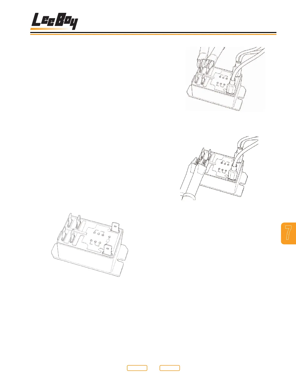
First Terminal Set Testing
Figure 7-18
Second Terminal Set Testing
Figure 7-19
NOTE: Without 12vdc applied to the coil of the relay,
the contact terminals should have no continuity
through them. The contacts should be “open”.
If the contacts are closed, and you do not
have 12vdc applied to the coil of the relay, your
contacts are not correct, and the relay should be
replaced.
2. With the ohm meter still on the contact terminals,
apply 12vdc to the coil terminals of the relay (Figure
7-18).
NOTE: The contact terminals should now close and
show a path through them for the power to be
applied to the electrical elements. If the relay
does not work as described above, it may be
faulty, and should be replaced.
Generator Capacitor
Replacement
The capacitor (Figure 7-15,1) located in the rear of
the generator controls and regulates the voltage in the
generator while in operation. If this capacitor fails, the
voltage will drop to little or no output at all.
Replacing this capacitor with one of the same type and
value will help determine if the capacitor is at fault.
To replace generator capacitor:
1. Ensure that the paver and generator engines are off.
2. Detach the wires at the top of the capacitor.
3. Remove the capacitor and replace with a new one
of the same type and value.
4. Re-attach the leads at the top of the capacitor.
There are no other voltage adjustments that can be
made to the generator.
Testing Element Relays
The element relays are 12vdc controlled, and have dual
contacts rated for 240VAC.
To test element relay:
1. Disconnect any wires to the relay, or completely
remove it from the control box (Figure 7-17).
Relay
Figure 7-17
Place the leads of an ohm meter, or continuity tester
across the contact terminals (2 to 4) or (6 to 8) as shown
in Figure 7-18; Figure 7-19.
Return to
Last Viewed
Return to
Thumb Index