7-20 LeeBoy Model 8510B Conveyor Paver
Maintenance
Battery Servicing
Burn Hazard! Batteries contain sulfuric
acid.
• NEVER allow battery uid to come in contact with
clothing, skin or eyes. Severe burns could result.
• ALWAYS wear safety goggles and protective
clothing when servicing the battery.
• If battery uid contacts the eyes and/or skin,
immediately ush the affected areas with a large
amount of clean water and obtain prompt medical
treatment.
The paver electrical system is a 12-volt negative ground
system. Keep sparks and ames away from the battery
as electrolyte gas is highly ammable. The battery is
located on the right side of the operator’s platform
behind the disconnect switch.
Fire Hazard! Keep sparks and ames
away from the batteries, as electrolyte gas is highly
ammable.
NOTE: When replacing the battery, discard the old
battery properly.
Always turn the master battery switch
off when working on the electrical system or welding
on the LeeBoy Model 8510B Conveyor Paver.
Damage to electrical components could result.
Before connecting the batteries, turn off the master
switch, located underneath the main dash panel.
Be certain that the terminals and battery posts are
thoroughly cleaned and that the battery cable terminals
are tight. Dirty or loose connections can create high
electrical resistance and permit arcing.
NOTE: The electrical system is a negative ground
system. Connect the positive (+) cable to the
positive (+) post of the battery. Connect the
ground cable to the negative (-) post of the
battery. It is advisable to disconnect the negative
(-) cable rst and connect it last. Reversed
polarity can damage the electrical system.
Keep the battery clean by washing it off whenever dirt
builds up is excessive. If corrosion is present around
terminal connections, remove them and wash with
ammonia solution or a solution consisting of 1/4 lb. (0.11
kg) baking soda added to one quart of warm water.
Element Resistance Testing
When a breaker in the control box has tripped, it must be
assumed that there may be a problem with wiring or an
actual element in the circuit.
Elements used to heat the screed are sized depending
on how much area and material they are required to
heat. The actual resistance of the element will vary
depending on what wattage the element is in the specic
application.
To know that the element is correct, you should read
a resistance between 28 ohms and 60 ohms. If the
element is bad, the reading will be very different from
this range. The element that is bad will most likely read
“open” or it will read very little resistance (less than 1
ohm) and will indicate a short through the element.
To test element resistance:
1. Disconnect elements one at a time from the
connection point on the lower side of the control
box.
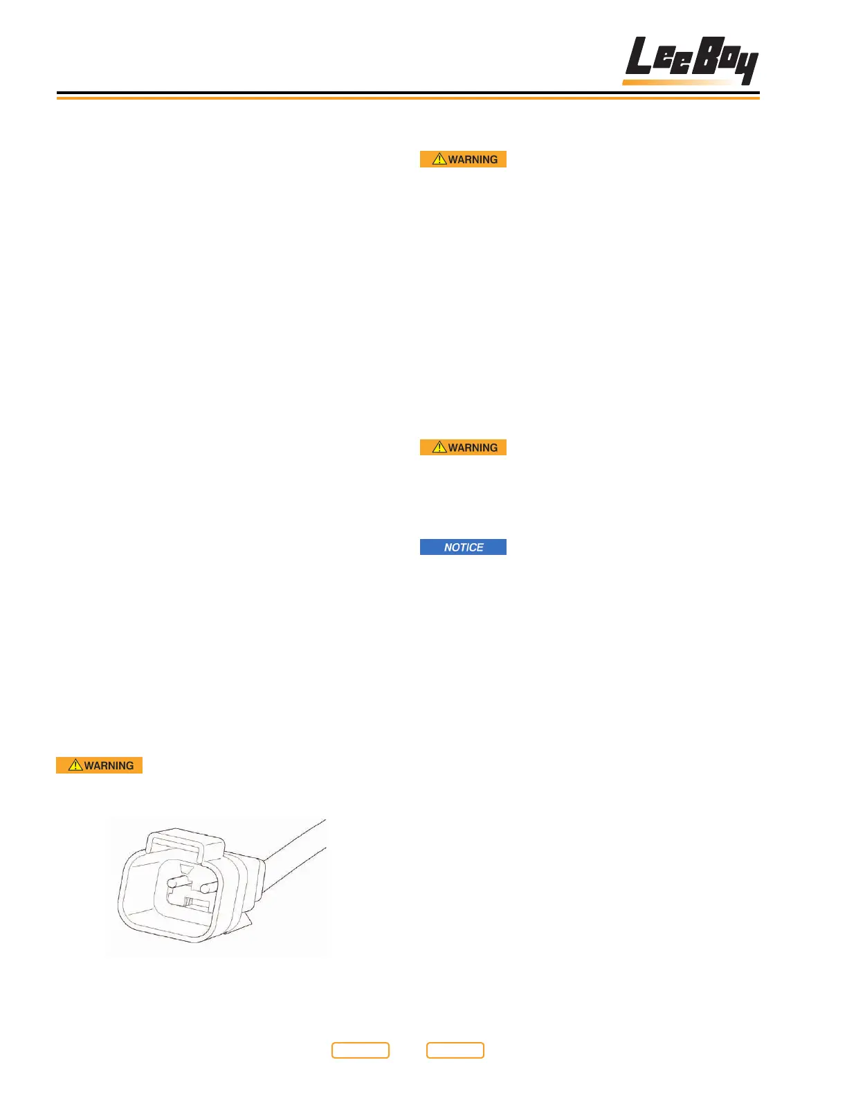
2. Use an ohm meter and test the resistance through
the element between the two pins in the plug at the
end of the element cable (Figure 7-20).
NOTE: You do not have to test the plug attached to the
lower side of the control box.
3. Test between the two pins shown here with an ohm
meter.
4. Test plug at end of element wires.
5. Before the element is plugged back in, check each
wire (pin) with an ohm meter test lead, and place
the other lead on a bare steel section of the screed
frame. If there is any continuity through the element
to the frame, the element is bad and must be left
disconnected or replaced.
Fire Hazard! Do not attempt to operate
an element with a known short. Replace faulty
elements and wiring before using.
Element Plug End
Figure 7-20
Return to
Last Viewed
Return to
Thumb Index