7
LeeBoy Model 8510B Conveyor Paver 7-15
Maintenance
Conveyor Limit Switch
Adjustment
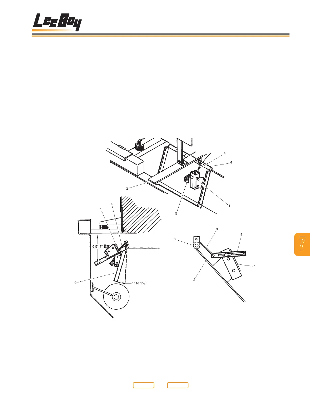
In order for the conveyor’s start and stop to occur at the
correct position, small adjustments may be necessary
to the micro-switch (Figure 7-12,1) located on the
conveyor ap (Figure 7-12,2). There are two positions
of the conveyor ap: one upper, shutting the conveyor
OFF, and one lower, turning the conveyor ON. Read the
following procedures carefully, referring to the gures
as needed.
1. Raise the conveyor ap (Figure 7-12,2) 6-1/2 to 7
in. (16.5 to 17.8 cm) from bottom of the tank mount
support (Figure 7-12,3). Secure conveyor ap so
Conveyor Micro-Switch Location
Figure 7-12
it remains in this position. If micro-switch clicked
OFF within the 6 1/2 to 7 in. (16.5 to 17.8 cm) limit, no
further adjustment is required to the upper travel.
2. If the micro-switch (Figure 7-12,2) did not click OFF,
adjustment is needed. Remove the linkage (Figure
7-12,4) attaching the actuator arm (Figure 7-12,5)
to the eyelet on the ap pivot housing (Figure
7-12,6).
3. Loosen setscrew “A” (Figure 7-13,1), on the
actuator arm (Figure 7-13,2). Reposition this arm
by either rotating it clockwise or counterclockwise
depending where the micro-switch clicked OFF
during the conveyor aps upward travel (see Figure
7-13).
1 - Microswitch
2 - Conveyor Flap
3 - Tank Mount Support
4 - Linkage
5 - Actuator Arm
6 - Flap Pivot Housing
Return to
Last Viewed
Return to
Thumb Index