6-22 LeeBoy Model 8510B Conveyor Paver
Operation
Element Breaker
The breakers are wired into each leg of each element.
If an element has a fault, either in the wiring, or in the
element itself, the breaker will trip and power will
no longer be applied to that leg of the element. The
breakers can be manually reset by depressing the trip
button back in when they are extended. If by depressing
the breaker re-set, the breaker will not reset, there
may be a need to replace the breaker, or diagnose the
element, or element wiring, it is connected to.
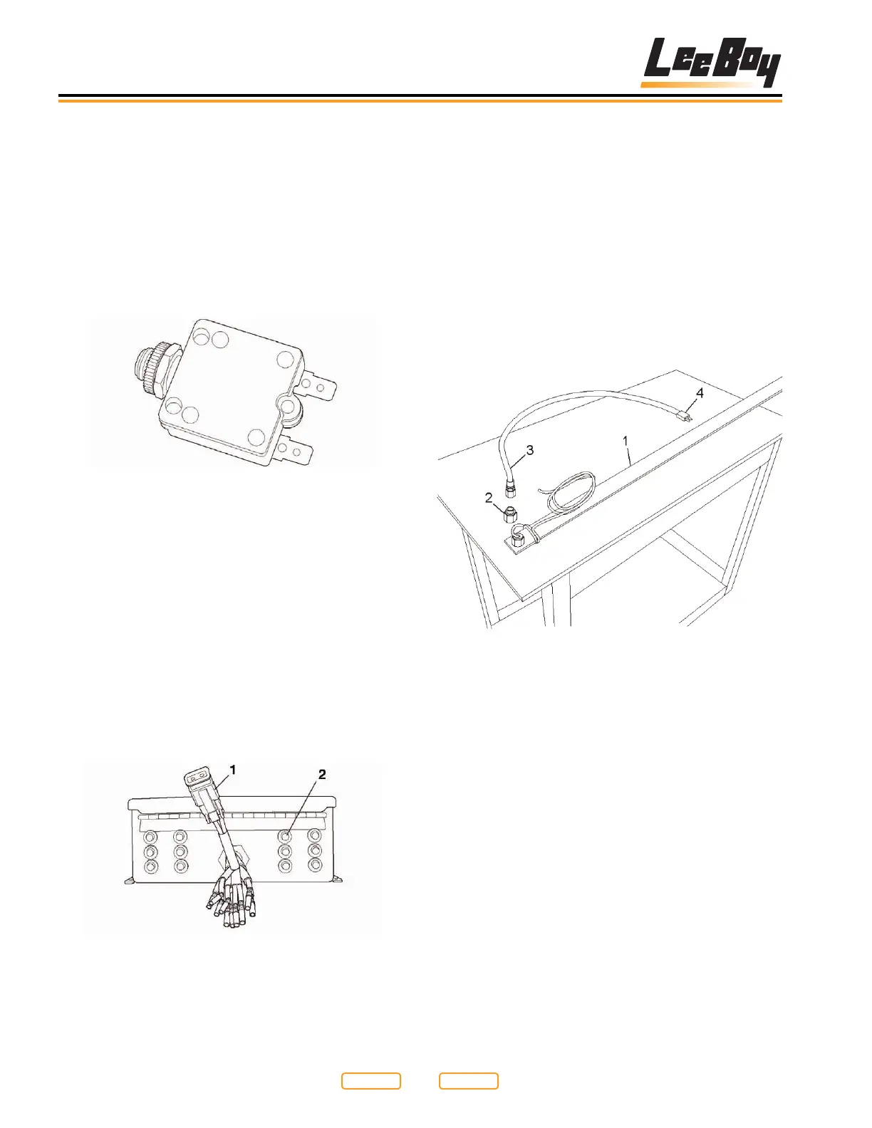
Element Breaker
Figure 6-27
Element Connections
The bottom of the control box contains the system
element breakers, and the 6 main outputs for the screed
heating elements (Figure 6-28). Since the heating
elements are powered by 220VAC to 240VAC, each
element has two breakers (Figure 6-28,2). There is one
breaker for each leg of each element. Also shown is one
of the two pin plugs that supplies power to the screed
elements.
NOTE: Any element lead can be plugged into any supply
plug (Figure 6-28,1) under the heating control/
distribution box. All six plugs are equally rated.
Electric Heat Control Box Bottom and Breakers
Figure 6-28
1 - Element Lead
2 - Breaker
Element Assembly
Next in the electric screed heating system are the
screed heating elements themselves. Each element is
sized to t properly in your screed, and provide sufcient
power to heat your screed plate to a temperature that
mix will not drag or stick to the lower surface of the
screed plate.
An element assembly consists of four main components.
The element (Figure 6-29,1), the wire protector adapter
(Figure 6-29,2), the wire protector (Figure 6-29,3),
and the two pin wire plug (Figure 6-29,4) at the end of
the element protector (Figure 6-29,3).
Heating Element Assembly
Figure 6-29
1 - Element
2 - Wire Protector Adapter
3 - Wire Protector
4 - Two Pin Plug
Each element (Figure 6-30,1) used has a thin strip of
insulation (Figure 6-30,2) over it to keep the heat of the
element from escaping. A support bar (Figure 6-30,3)
is then laid over the element, and a shield (Figure
6-30,4) protects the element assembly. Each element
is clamped down to the screed plate so as to provide a
positive and efcient connection between the element
and the screed plate.
Return to
Last Viewed
Return to
Thumb Index