6
LeeBoy Model 8510B Conveyor Paver 6-21
Operation
Cycle Timer
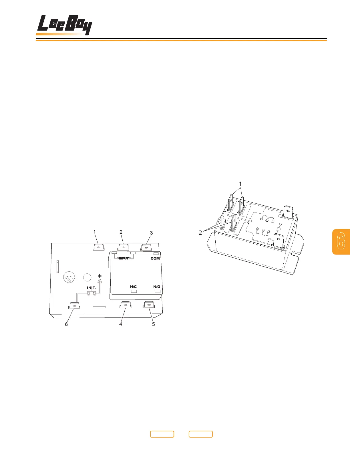
A heat system timer is shown (Figure 6-25). There are
six terminals on the timer. The top two left terminals are
the main 12 vdc input terminals for the timer. The ground
(Figure 6-25,1) is on the left and the power (Figure
6-25,2) is on the right.
The top right terminal is the common terminal (Figure
6-25,3) to the internal timer relay that controls the heat
system. When power is applied to the input terminal, it
is also jumped to the common (or COM) terminal on the
timer. The lower right two terminals on the timer are the
outputs of the internal timer relay.
The left of these two is the normally closed terminal
(Figure 6-25,4), which is not used in this system, and
the lower right terminal (Figure 6-25,5) is the normally
open terminal. The normally open terminal is used as
the output terminal to “turn” the heating system on. The
lower left hand terminal (Figure 6-25,6) is the “initiate”
contact. When the HEAT ON button (Figure 6-8,2) is
depressed, 12 vdc is momentarily applied to this terminal
to start the timer cycle. During the timer cycle, power
will not be applied to this terminal unless the HEAT ON
button (Figure 6-8,2) is depressed again. Keep in mind,
if this happens, the timer will restart.
Heat System Timer Terminals
Figure 6-25
1 - Ground Input
2 - Power Input
3 - Common (COM)
4 - Terminal Output
5 - Terminal Output
6 - Initiate Terminal
Element Relay
Each element output from the bottom of the box consists
of two wires. One wire will connect to the L1 circuit, and
the other wire will connect to the L2 circuit. The L1 circuit
is the left bank of element breakers. Each breaker has
two terminals. One terminal is connected to the main
input, and the other terminal is connected directly to an
element output wire. The L2 circuit is the right bank of
element breakers. This bank is wired slightly different,
in that each leg not only goes from the main L2 power
lead through a breaker, but each leg then goes through
one of the six contacts on the element relays. It is these
relays that “make” or “break” the circuit to each element
to start or stop the heating cycles.
An element relay is shown here (Figure 6-26). There
are three relays in the control box. Each relay has two
separate sets of contacts operated by one coil.
Element Relay
Figure 6-26
1 - Coil Terminals
2 - Contact Terminals
The coil contacts on the relay shown are at the top
and bottom of the right hand side of the relay (Figure
6-26,1). One set of contacts are the two terminals at the
top left of the relay, and the other set of contacts (Figure
6-26,2) are at the bottom left of the relay shown. When
the coil is energized, both sets of contacts will close.
All the relays used are “normally open” (see Testing
Element Relays in Section 7).
Return to
Last Viewed
Return to
Thumb Index