6
LeeBoy Model 8510B Conveyor Paver 6-23
Operation
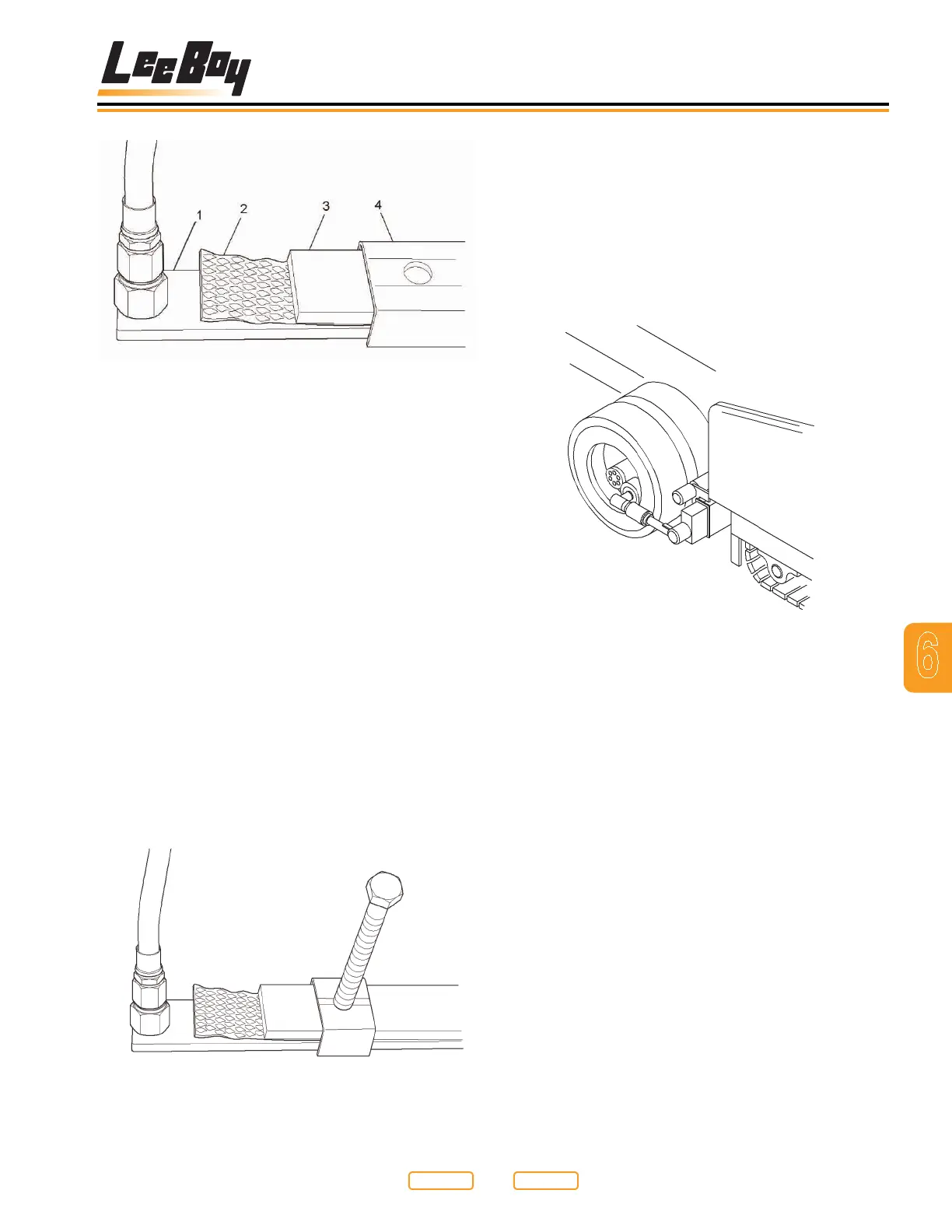
Heating Element Assembly Detail
Figure 6-30
1 - Element
2 - Insulation
3 - Support Bar
4 - Shield
A typical element clamp assembly is shown (Figure
6-31). The clamp setup may vary slightly depending on
your screed size, or whether you are working on the
extension or main screed plates. The principle is the
same with all of the clamps.
Enough pressure should be applied to the element
assembly to sufciently hold the element tight against
the screed plate surface. All clamp setups are lockable
with a jam nut on the adjustment screw. After tightening
the clamping stud, lock the clamp by tightening the stud
jam nut. To remove an element, loosen all the clamping
studs over the element, and then the element can be
removed from the frame through the access provided at
the outer end of the screed. The extension elements are
accessed by removing the top cover from the extension
screed plate.
Typical Heating Element Clamp
Figure 6-31
Truck Hitch Attachment
(Option)
The truck hitch is an optional attachment. It was
designed to improve the asphalt laying process. This
is mainly accomplished by keeping the truck driver off
his brakes, preventing excessive and uneven braking.
To engage the hitch with the rear wheels of the asphalt
truck, proceed as follows:
Truck Hitch Option
Figure 6-32
1. Extend the arm extensions of the truck hitch by
setting the TRUCK HITCH IN/OUT Lever (Figure
5-5,1) to the OUT (Down) position to extend the
hitch arms.
2. Slowly drive paver toward rear of truck until roll on
hitch makes contact with the rear tires of the truck.
3. Retract the arm extension by setting the TRUCK
HITCH IN/OUT Lever (Figure 5-5,1) to the IN (Up)
position to retract the hitch arms until both guide
rollers are fully locked into truck wheel rims.
4. It may be necessary to adjust the roller guides to the
inside of the wheel rims, initially.
Return to
Last Viewed
Return to
Thumb Index