7
LeeBoy Model 8510B Conveyor Paver 7-9
Maintenance
Maintenance
Adjustments
Extension Top Guide Adjustment
1. Close the left and right extensions to their fully
retracted positions.
2. Loosen top jack bar bolts.
3. Use allen set screws on top of rail to tighten the
upper slide guide rail down. Access the upper slide
guide rails through the small openings in the upper
cover near the front of the main screed frame. Start
at the outside of the paver, and work to the center.
4. Retighten top slide rail bolts.
5. Check for binding - do not overtighten set screws.
6. Run the extensions out fully and grease the slide
track rails.
NOTE: The slide tracks should be greased daily to help
prevent excessive wear.
Replacing Screed Extension
Wear Plates
Removal
1. Run extension out fully.
2. Remove endgate by disconnecting tilt screw and
loosen the 7/8” jam nut.
3. Remove nut. Endgate will drop forward out of slot
and slide off of stud.
4. For units with electric heating units. Locate and
unplug the element power wire. Make certain the
wire running into the extension screed is loose and
will drop away when the screed plate is removed
with interference.
5. Remove shoulder bolts out of lower adjustment
screws on top of wear plate (Figure 7-4,1).
6. Closely inspect all plugs, pins, and wires for
damage. Replace if needed.
7. Lower screed to ground and pull front pivot pin out
on 8510B (Figure 7-5).
8. Lift screed and wear plate should be disconnected.
1
Wear Plate Shoulder Bolts
Figure 7-4
1 - Adjuster Screw Shoulder Bolt
Installation
1. Clean all areas where new wear plate will be
attached.
2. Place new wear plate in position with oor jack or by
lowering screed to oor and slide pivot pin in.
3. Reconnect the element power wire and re-tie the
power cable to the attachment point provided.
NOTE: Do not tie the power cable so that it is tight. A
small amount of slack in the cable where it enters
the protective hose tting is required.
4. Attach adjustment screws to new wear plate.
5. Place endgate back on.
6. Adjust 7/8” nut so that endgate will move up and
down freely, then lock in place with jam nut.
7. Connect tilt screw.
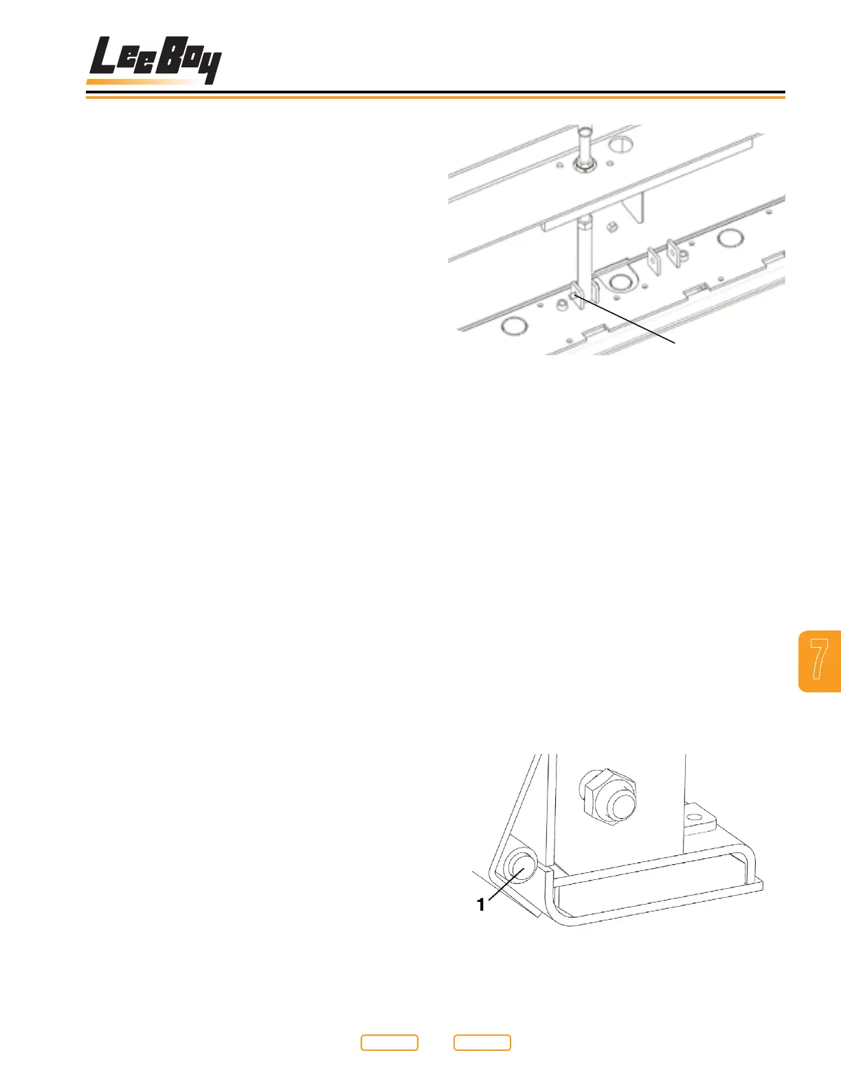
8510B Pivot Pin
Figure 7-5
1 - Extension Wear Plate Pivot Pin
Return to
Last Viewed
Return to
Thumb Index