6-20 LeeBoy Model 8510B Conveyor Paver
Operation
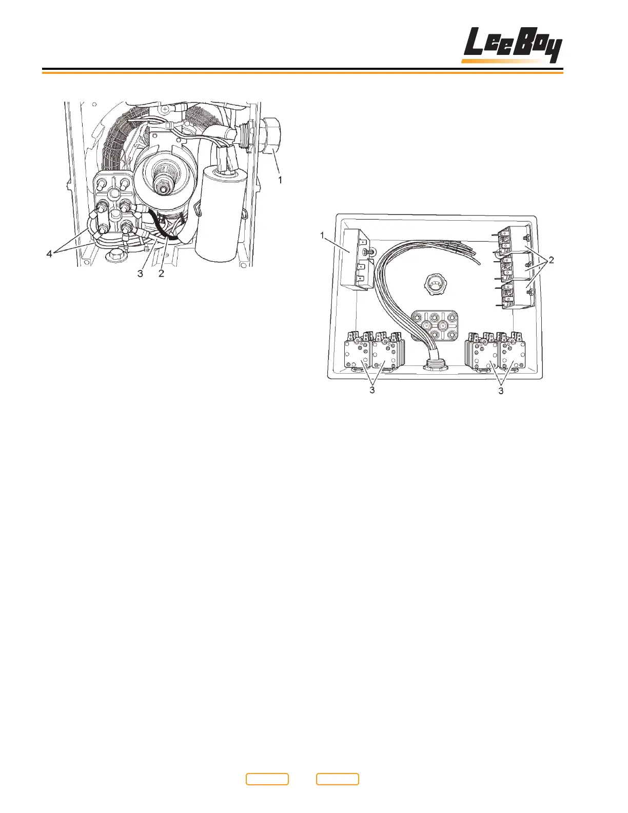
Generator Rear View
Figure 6-23
1 - Power Cable
2 - L1 (Black Wire)
3 - L2 (White Wire)
4 - Generator Winding Wire
The rear of the generator is shown in Figure 6-23.
You can see the power cable (Figure 6-23,1) coming
into the generator case at the top right. Just below the
generator case is the voltage capacitor. The capacitor
controls the output voltage of the generator, and may
need to be changed if no voltage is generated by the set
(see Generator Voltage Testing in Section 7).
The main output of the generator is located in the lower
left of the picture. You will see two main wires attached
to the generator, a black wire (Figure 6-23,2), and a
white wire (Figure 6-23,3). The other two wires (Figure
6-23,4) are generator winding wires, and should not
need to be serviced under normal circumstances.
Control Box
NOTE: All control boxes are manufactured the same
to t all screed and paver combinations. If your
screed does not have enough element wires
to ll all the plugs on the bottom of the control
box, it may be normal. Any plugs that are not
lled should be capped with appropriate plug
terminator.
Electric Heat Control Box Before Wiring Completed
Figure 6-24
1 - System Timer
2 - Element Relays
3 - Element Breakers
The control box consists of three major types of
components. The system timer (Figure 6-24,1) is
located in the upper left hand corner of the box. The
element relays (Figure 6-24,2) are located in the upper
right hand corner of the box, and the element breakers
(Figure 6-24,3) are located in the lower surface of
the box. The other block in the center is used as a wire
junction block only (see Schematics in Section 9).
Return to
Last Viewed
Return to
Thumb Index