7-16 LeeBoy Model 8510B Conveyor Paver
Maintenance
Electrical System
Use compressed air to blow dirt from
generator monthly or more often if used in dirty
environment. Do not use high pressure water.
Always make sure work area is clean
and free of any water before working on electrical
system.
Generator Voltage Testing
The LeeBoy Model Legend Electric Screed System
generator is hydraulically driven. When the paver
engine is at full rpm and the hydraulic system at normal
operating temperature, the generator should produce
between 220VAC and 240VAC.
The voltage of the generator depends on speed
(rpm). The voltage increases as rpm increases, and
decreases as rpm decreases. The voltage will decrease
signicantly if generator speed is slower than 3000 rpm.
NOTE: When testing the generator voltage ensure the
paver engine is at full rpm and the hydraulic
temperature is at normal operating levels.
To test the generator voltage at the generator:
1. Use volt meter to measure between the two main
input wires L1 and L2 (Figure 7-15,2,3). If you
measure from L1 to the frame of the paver, or
ground, the voltage will be half of the rated output of
the generator. The voltage should be the same as
measured at the control box.
To test the generator voltage at the control box:
1. Use volt meter to measure between the two main
black and white input wires located inside the
control box on the terminal block similar to one in
Figure 7-15. The voltage should be the same as
measured at the generator.
NOTE: If your voltage at this point is lower, make certain
the generator is turning the correct speed (see
Generator Speed Tuning in Section 7).
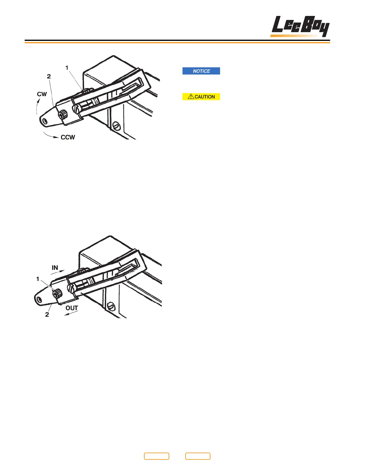
Setscrew “A” Location
Figure 7-13
1 - Setscrew A
2- Actuator Arm
4. When the click OFF occurs between the 6-1/2 to
7 in. (16.5 to 17.8 cm) limit, tighten setscrew and
connect linkage.
5. If the lower ap travel does not fall into the lower
limits, loosen setscrew “B” (Figure 7-14,1) on the
actuator arm (Figure 7-14,2) slightly.
Setscrew “B” Location
Figure 7-14
1 - Setscrew B
2 - Actuator Arm
NOTE: The setting from the factory is 1 in. (2.54 cm) from
the center of the setscrew “B” to the eyelet on
the actuator arm.
6. To bring the travel limits into tolerance, slide the
actuator arm in the direction desired. This may
require several adjustments before the correct
position is obtained. When the actuator arm is in the
correct position, tighten setscrew “B”. No further
adjustment is necessary.
Return to
Last Viewed
Return to
Thumb Index