121
03/10/2013MM00771-a-
H4648
LN4648
0 675 66
5 727 36
5 722 36
1
2
3
2 3
4
5 6
1
DC - In
MH201
MH201
EN
BUS SCS
RFID key card switches
Two modes:
- CENTRALIZED, to recall scenarios managed by the scenario programmer. When
the key card is inserted and removed, the device forwards a signal to the scenario
programmer, which depending on the scenarios set will activate the corresponding
functions programmed.
A = 1-9 (CEN command address)
PL = 1-9 (CEN command address)
M1 = CEN
DEL1 = no configurator
M2 = no configurator
DEL2 = no configurator
Note: the insertion of the key card corresponds to “Pushbutton 1” of the control, while
the removal of the key card corresponds to “Pushbutton 2” of the control
- SCENARIO, where by inserting the key card a group of actuators is enabled, and an
entrance scenario is activated (through the scenario module), and by removing the
key card an exit scenario is activated (through the scenario module), thanks to which
all the group actuators will switch off and then disable after a set time delay.
A = 1-9 (as scenario module)
PL = 1-9 (as scenario module)
M1 = 1-8 (activation of the corresponding scenario: see table B)
DEL1 = 0 - 9 (switching on time delay at the insertion of the key card: see table A)
M2 = no configurator
DEL2 = 0 - 9 (switching off time delay after the removal of the key card: see table A)
SCENARIO mode programming
This operation is performed to create a link between the key card switch and the
scenario module. The procedure is as follows:
1) Power the key card switch. Check that the scenario module is in programming
mode, with the green LED on;
2) Press and hold down programming key 1 (Learn IN) or 2 (Learn OUT) until the LED
starts flashing (approximately 3 seconds);
3) Create the scenario using the system controls and actuators;
4) Once the scenario has been saved, briefly press programming key 1 (Learn IN) or 2
(Learn 2) to exit the programming status;
5) The scenario module will also have to exit programming status (see the scenario
module technical information).
Cancelling the programming in SCENARIO mode:
1) Power the key card switch. Check that the scenario module is in programming
mode, with the green LED on:
2) Press and hold down programming key 1 (Learn IN) or 2 (Learn 2) for 8 seconds.
after 3 seconds the LED will turn on, after a further 5 seconds it will turn off again;
3) Release the key;
4) The LED flashing, followed by the LED switching off, indicates that the programming
has been cancelled;
5) The scenario module will also have to exit programming status (see the scenario
module technical information).
Note: Sce 1 = scenario activated on insertion
Sce 2 = scenario activated on removal
Gr = group of actuators
Physical configuration
SCENARIO mode programming
Table A
Configurator value Time
0 0
1 1 min
2 2 min
3 3 min
4 4 min
5 5 min
6 10 min
7 15 min
8 15 sec
9 30 sec
Table B
Congurator value Scenario - Group
1 Scenario-group (Sce1=1, Sce2=9, Gr=1)
2 Scenario-group (Sce1=2, Sce2=10, Gr=2)
3 Scenario-group (Sce1=3, Sce2=11, Gr=3)
4 Scenario-group (Sce1=4, Sce2=12, Gr=4)
5 Scenario-group (Sce1=5, Sce2=13, Gr=5)
6 Scenario-group (Sce1=6, Sce2=14, Gr=6)
7 Scenario-group (Sce1=7, Sce2=15, Gr=7)
8 Scenario-group (Sce1=8, Sce2=16, Gr=8)
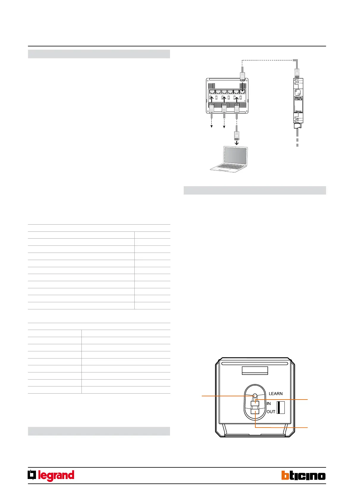
1. Programming key: Learn IN
2. Programming key: Learn OUT
3. LED
Ethernet connection to the system
HUB Switch
BUS-SCS
PC for conguration
Ethernet network
Ethernet
network
This is performed using the appropriate MyHOME_Suite application. This mode has
the advantage of offering many more options when compared with the physical
configuration. The software configuration requires Ethernet connection between the
system and the PC, through the IP MH201 scenario module.
Configuration using the MyHOME_Suite software