315
P
M1
PL1/N1
A
A2/-
PL2/N2
M2
HD4577
HC4577
HS4577
L4577
N4577
NT4577
Description
The radio interface is indispensable to receive the temperature data transmitted by the
radio probe. Up to two probes can be associated with each interface thus giving the
system two measuring points for each interface. Up to nine temperature probes can be
installed in a system.
Both the interface and the communication probe use radio waves with a frequency of
868 MHz. The maximum distance of communication between the receiving interface and
the temperature sensor is 70 m in free air. This distance is less if there are walls in cement,
metal or other material between the devices.
Technical data
- Power supply from SCS BUS: 27 Vdc
- Operating power supply with SCS BUS: 18 – 27 Vdc
- Max. absorption: 33 mA
- Operating temperature: 0 – 40 °C
- Radio frequency: 868 MHz
- Range: 70 m in free eld (metal walls and surround plates
and reinforced concrete walls reduce the range);
- Size: 2 ush mounted modules
Conguration
In order to use a receiving interface and radio probe, conguration must rst be performed,
followed by the programming procedure. Only the interface needs conguring. Up to 2 probes
may be combined with each interface, therefore providing the system with two detection
points for each interface. Up to a maximum of 9 temperature sensors may be installed in one
system.
The conguration sockets on the interface identify the radio probes address.
They are: A1/-, PL1/N1, M1 for the rst address, and A2/-, PL2/N2, M2 for the second address.
The two addresses must always be dierent from each other, PL1/N1 ≠ PL2/N2. Only one radio
probe may be associated to each address. Only used addresses must be congured.
The interface must be congured in temperature control mode by connecting
congurator 1 to M1 and M2. With this mode the A1/- and A2/- sockets are not used, therefore
no congurator needs to be connected.
Programming of devices:
After performing the conguration, it will be necessary to associate The radio probe to
the interface following the programming procedure below:
1) Press the pin pushbutton of the interface for 5 seconds. The red LED turns on.
Release the pushbutton. The interface LED will ash every two seconds to conrm
that programming mode is active on the rst address (group of congurators
PL1/N1, M1). If the second address of the interface is not congured (no congurator
is connected to the PL2/N2, M2 positions), go to step 2 of the procedure.
However, if also the second address must be congured (group of congurators
PL2/N2, M2), simply press the pin pushbutton of the interface again.
The LED will ash twice in succession every two seconds.
Every time the pin pushbutton is pressed, the system will switch from the rst to the
second address and vice versa.
2) After choosing the address the radio probe should be associated to, within 20 seconds
press the transmission key of the probe itself. Pressing the transmission key will send
the probe serial code. After receiving the code through the radio signal, the red LED
of the interface will quickly ash for 2 seconds, conrming that programming is
complete, and the procedure has been terminated.
If necessary repeat the operation, to save the code of another probe. If on the other hand
an address has already been associated and the procedure is repeated with another
probe, the interface performs an overwriting action, only keeping the last probe in
the memory. During normal operation, the sending of information from the probe is
conrmed by the ashing of the red LED of the interface. A single ashing indicates that
the radio message has been received, and the “temperature” data has been sent through
the BUS by a probe associated to the PL1/N1, M1 address. A double ashing indicates
that the radio message has been received, and the “temperature” data has been sent
through the BUS by a probe associated to the PL2/N2, M2 address. To delete all codes
from the interface press the pin pushbutton for 12 seconds. After 5 seconds from pressing
the key, the LED will turn on steadily, and after a further 7 seconds, it will start ashing
quickly, conrming that all programs have been deleted.
NOTES:
- If the interface conguration is wrong, the red LED will ash. Correct the conguration.
- If the second interface address has not been congured (no congurator connected to
the PL2/N2, M2 sockets), during the programming procedure it will not be possible
to switch to this address, which therefore cannot be programmed.
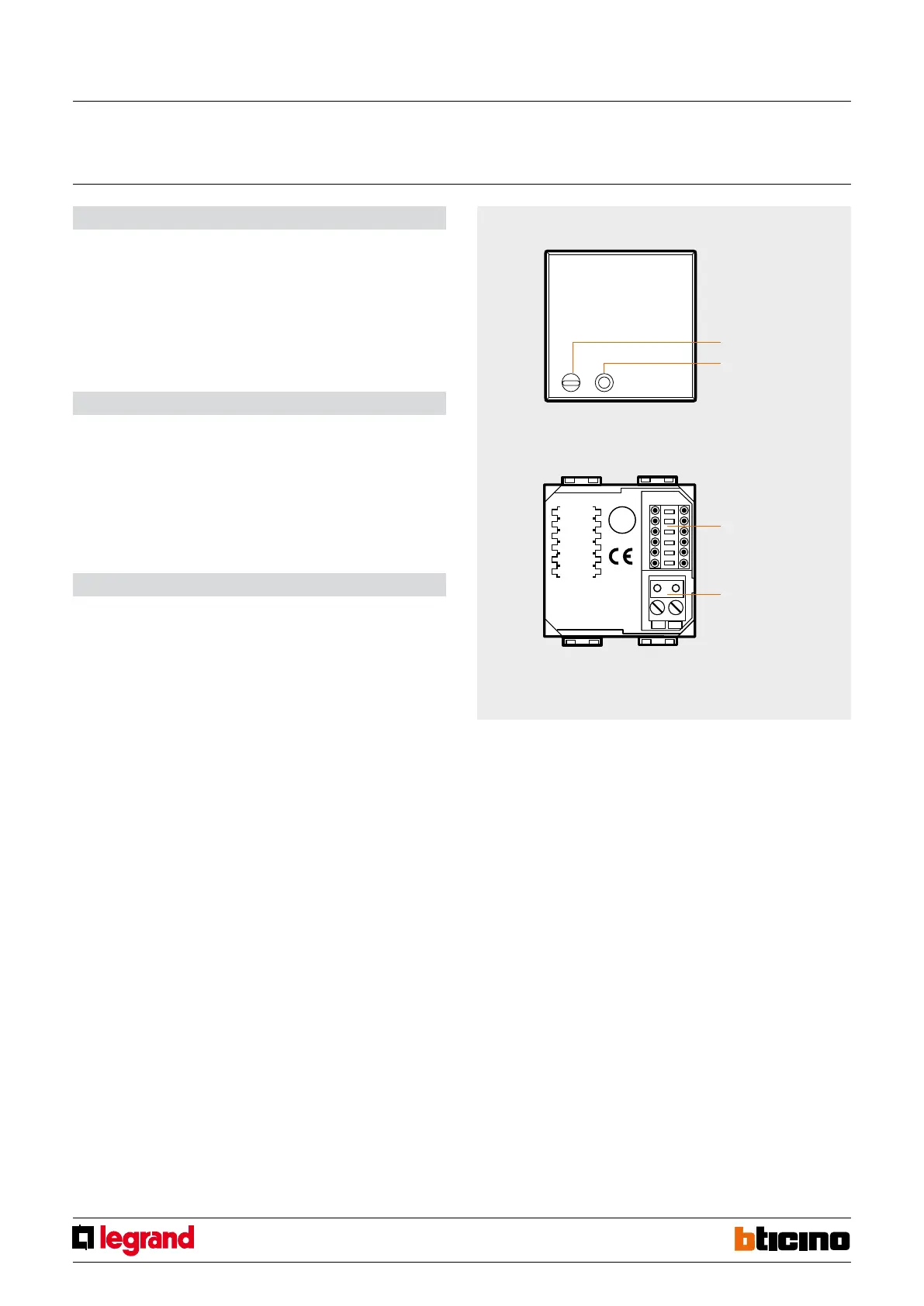
Front view
LED
programming
pushbutton
Rear view
congurator
socket
BUS
Radio interface
for outdoor temperature probes
MQ00183-c-EN 29/04/2014