265
1 2
N°
MOD
Z
AUX
N°
MOD
Z
AUX
N°
MOD
Z
AUX
N°
MOD
Z
AUX
N°
MOD
Z
AUX
4
1
HD4607
HS4607
L4607
N4607
NT4607
AM5787
HC4607
573949
067508
573948
Description
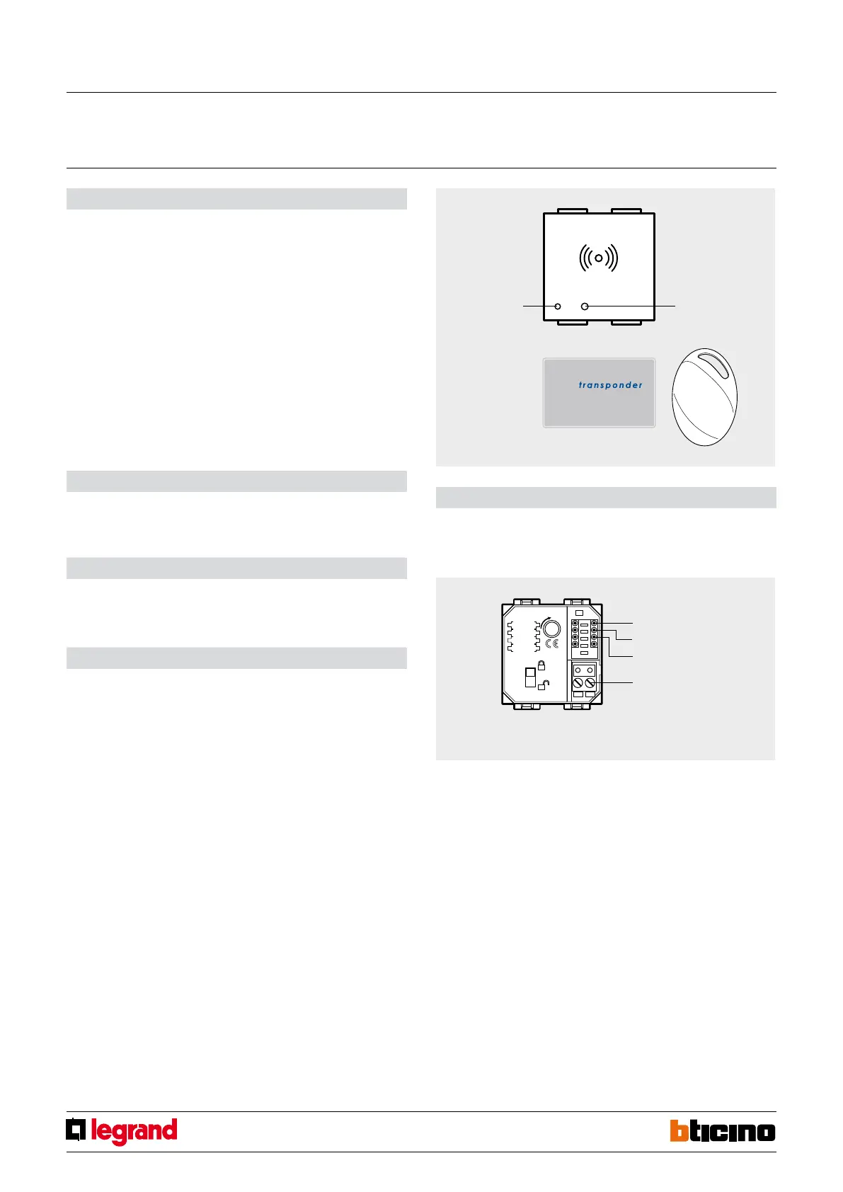
The transponder reader is a device which activates when the Transponder badge (3530S
or 3540) is in its immediate vicinity (1-2 cm). The signal generated by the approach of the
badge is then transferred to the bus (BUS cable item L4669S). The transponder reader is
tted in the wire burglar-alarm system and works like a traditional activator; it is thus
connected to the BUS cable like any other burglar-alarm device.
The transponder does not need a power supply battery. When compared with the
traditional remote control, the “transponder reader/transponder system oers better
safety due to the code encryption system. Also, the possibility of saving up to 50 badges
(depending on the central unit used) oers better exibility in the management of
the system, particularly in those environments (companies, oces, shops), where the
number of people enabled to use the system is high and changes regularly.
Related articles:
681 84 (White Cover)
684 84 (Titanium Cover)
Legend
1 - Three-colour LED for operation indications;
2 - Reset pushbutton (NOT ACTIVE).
Technical data
- Power supply from SCS BUS: 27 Vdc
- Max. absorption: 12 mA
- Operating temperature: 5 – 40°C
Dimensional data
Size: 2 modules
Conguration
BURGLAR-ALARM mode:
The transponder reader used as burglar-alarm system activator/disconnector must be
assigned to the group of activator; it thus requests the assignment of the “group” number
attributed (see below) and the progressive number of the devices in the “group”.
Z
This congurator assigns the number of the appropriate zone in the “group” of devices
(any free zone in the system). To congure it as belonging to the group of activators, no
congurator must be inserted.
- Congurators 1, 8 instead would assign the transponder reader to the sensor (IR
detectors or contact interface) “group” while congurator 9 would assign it to the
“group” of auxiliary devices (auxiliary channel interface or relay actuator).
N°
This congurator assigns the progressive number of the transponder reader inside the
zone attributed. Congurator 1 identies the rst reader-transponder, congurator 2 the
second and so on until a maximum of 9 receiver devices for each of the zones.
MOD
Assigns the operating mode. It assigns the operating mode. In order for it to operate
as activator, use congurator 1 with ush mounted central units item 4600/4, and
congurator 0 for other central units.
The transponder is saved in the burglar-alarm central unit. The maximum number that
can be managed is:
- 29 with ush mounted central unit, item L/N/NT4600/4.
- 50 with central unit with display, item 3486 or 3485, 573935, 573934, 067520.
- 20 with central unit with display, item 3485B or HC/HD/HS/L/N/NT4601.
Front view
Z
Clamp for burglar
alarm BUS
No.
MOD
Rear view
NOTE: when all the 9 devices allowed have already been inserted in the group of
activators, a value between 1 and 9 could be assigned to congurator Z (appropriate
zone) taking account of the progressive No.
Transponder reader
MQ00033-c-EN 24/04/2014