327
OKC
2
3
4
5
6
1
9
7
8
SLA
ZB
ZA
20.6
°C
02 : 45 Mar 22 Ago
18.0
°C
10
11
12
HC4695
HS4695
L4695
N4695
NT4695
AM5875HD4695
Description
This central unit can manage MY HOME temperature control systems with up to 4 zones,
with a maximum of 9 circulation pumps. It can control heating or cooling systems and
can set the system and modify the system operating mode.
The central unit is made up mechanically of two parts: a base to fasten on the supporting
frame for wall mounted boxes to which the bus is connected and a removable front cover
for easy programming with the settings required. The device communicates with and
is supplied by the bus, while the two AA batteries supply power when the removable
part is not inserted in the supporting frame. The central unit has a probe which already
represents a system zone and the conguration sockets are in fact on the back part.
Another three probes can be connected to reach the absolute number of zones which
the system can manage in this case (a maximum of 4 zones in total). Coming with
management software with guided menu shown on the display, it lets the user select
the operating mode, display the temperatures of the various zones and display and
modify the daily temperature proles and the weekly programs; the maintenance menu,
reserved to the installer and code protected, allows access to the system settings (zone
conguration, system test, total reset, etc.).
The temperature central unit has a graphic display with blue back-lighting in the
AXOLUTE series and green back-lighting in the LIVING, LIGHT, LIGHT TECH and Màtix
series. By means of the six keys on the device front cover all the functions can be used
interacting with the various menu items. The complete programming of the central unit
by PC can be activated through the serial connector and the TiThermo BASIC software.
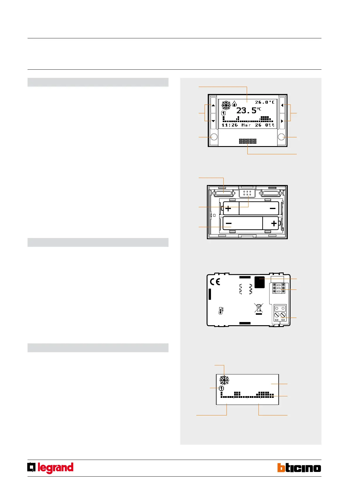
Legend
1. Graphic display: displays the system state and guides the programming operations.
2. Selection keys: can set the operating mode and select the functions.
3. OK key: to access the main menu or conrm the selection displayed.
4. Sensor: to measure the room temperature.
5. C key: to cancel the selection.
6. Scroll keys: to modify the temperature using the main screen;
to scroll the menu items.
7. Connector: connection to the electronics in the back base.
8. Serial connector: for connection to the PC and use of TiThermo BASIC.
9. Battery compartment: socket for 2 AA 1.5V batteries.
10. Screw: to block central unit extraction.
11. Congurator socket: socket of the congurators for the combined probe.
12. BUS: connection for cable bus.
Technical data
- Power supply from SCS BUS: 27 Vdc and 3 Vdc (2 AAA type, 1.5 V batteries)
- Operating power supply with SCS BUS: 18 – 27 Vdc
- Absorption: 30 mA with the light on
- Absorption: 8.5 mA with the light o
- Operating temperature: 0 – 35 °C
- Size: 2 modules
- Installation height: 1500 m from the oor
Graphic display
During normal operation the central unit graphic display shows the system basic
information, while the screen light stays o. When a key is pressed, the display illuminates
and the central unit is ready to implement any instructions entered by the user.
Plug-in section
front view
Plug-in section
back view
Fixed section
back view
measured
temperature
daily prole
date
Summer/Winter
system state
weekly
program
hour
4-zone central unit
MQ00178-c-EN 29/04/2014