205
T
C
-
T
C
-
1 m
(*)
3444
Conguration
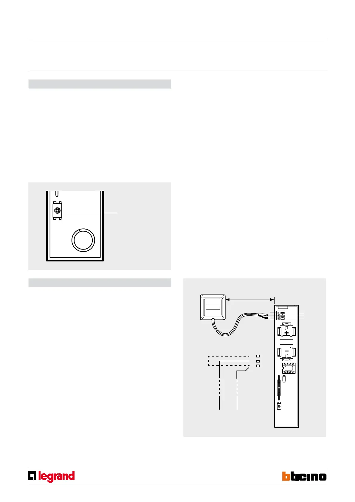
Pairing detectors
1. Switch the system to “maintenance” mode.
2. Press the programming pushbutton of the radio receiver for ve seconds, until the
red LED comes on.
3. Press the tamper contact twice.
4. If the pairing of the device has been performed correctly, the red LED of the receiver
will go o. If this does not happen, repeat the procedure from step 3. If the LED
ashes, it means that the device memory is full.
5. To pair other devices, repeat from step 2.
6. Close the sensors to deactivate the tamper.
7. Perform self learning of the system from the central unit.
8. Exit “maintenance” mode.
Wiring diagram
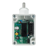
The sensor must be connected using the transmitting unit as shown in the gure.
Do not extend the probe cable.
Cancelling detectors
1. Switch the system to maintenance mode.
2. Remove the power supply from the radio receiver.
3. Press and hold the programming pushbutton while reconnecting the power supply to
the radio receiver.
4. After 5 seconds the LED ashes orange. If the pushbutton is released at this time, only
the remote controls are cancelled.
After 10 seconds the LED starts ashing quickly. If the pushbutton is released now,
only the sensors are cancelled.
5. After releasing the pushbutton, the LED becomes xed orange. When the LED goes
o, cancellation has been completed.
6. Perform self-learning of the system from the central unit and exit “maintenance”
mode.
Tamper/learning
Glass-breaking detector
To the glass-breaking detector
Tamper line
WARNING: For correct operation of the device the glass-breaking detector, or any
additional magnetic contacts, must be activated within 12 hours from the moment the
device starts operation.
Note (*): short circuit contacts – and T if no tamper line is installed
Radio glass-breaking detector
MQ00053-c-EN 28/04/2014


 To Next Page