215
BUS
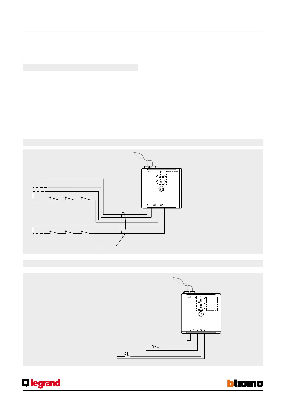
N.C. N.C. N.C.
N.C. N.C. N.C.
BUS
3480
Energy saving management with Temperature control
If the contact interface is used in conjunction with the temperature control system to optimise
energy saving, two dierent types of congurations will be possible:
- Use in the temperature control system only: The contact interface is directly
connected to the temperature control BUS. It autonomously and independently
manages the two C1 and C2 lines. Only the line used must be congured, and not
both of them. Follow by connecting the AUX congurator to the MOD1 and/or MOD2
sockets. Then congure the [Z1/2] and [N1/2] sockets, in order to assign the address
from 1 to 99 to the device within the system.
The coupling between the interface contact line and the temperature control zone
must be performed using the TiThermo application. For more information refer to
the MY HOME Temperature control guide.
- Use of a burglar-alarm system integrated with the Temperature control
system: in this case, the contact interface is connected to the burglar-alarm system
BUS only, and communicates with the temperature control system BUS through the
F422 interface.
The interface must be congured in Z1/2 and N1/2 following the requirements and
features of the burglar-alarm system; only congurators with values 4 to 7 must
be connected to the MOD1/2 position, corresponding to the management of NC
contacts with generation of AUX event (see tables above). Also in this case, the
actual coupling between the interface contact line and the temperature control
zone must be performed using the TiThermo application. For more information refer
to the MY HOME Temperature control guide.
Balance resistance
68 kΩ ±5% 1/4 W
Balance resistance
68 kΩ ±5% 1/4 W
NOTE: It is recommended to install the
68 kΩ ±5% 1/4 W balancing resistance in
correspondence with the last line contact.
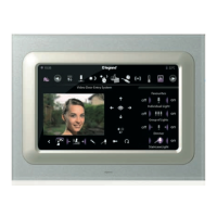
Used for managing a technical alarm
Wiring diagram
(
*
) The N.C. pushbutton can be replaced by a NO pushbutton. The type of
pushbutton activating the alarm is dened through the conguration of the MOD1
position of the device.
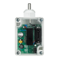
It is possible to also connect a water detection probe, as well as NC/NO contacts for
smoke or gas detectors. For the water detection probe use item 3482.
Alarm Reset
N.O. pushbutton
N.C. pushbutton (
*
)
Technical alarm activation
WARNING: use a 30 m max twisted, unshielded
cable.
Unshielded
twisted cable
Tamper line
MQ00045-d-EN 28/04/2014
Contact interface


 To Next Page