222
+–A
3481
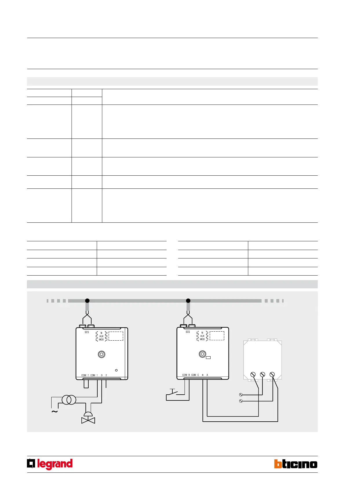
EXAMPLE: Activation of the solenoid valve in case of gas leak
Relay actuator conguration:
Congurator position Value
N° 1
AUX 1
MOD 6
Congurator position Value
N° 2
AUX 1
MOD 4
Technical alarm interface conguration
Wiring diagram
Burglar alarm BUS
To the gas detector
12 Vac
Activation from the technical alarm interface
Relay actuator
3479
Technical alarm
interface
3481
Transformer
Solenoid valve
Congurators
Relay opertating mode (description)
AUX MOD
1-9 none Technical alarm with NC contact and activation of the auxiliary channel
Internal siren (MOD 0 or 2) sounds intermittently until one of the following events occurs:
a) there is no longer an alarm;
b) the alarm is reset using the menu of central units with display (with central unit L/N/NT4600/4 press “S”);
c) the reset pushbutton connected to the interface is pressed.
It activates the corresponding auxiliary channel.
1-9 1 Anti-burglary automation with NC contact
It activates the corresponding auxiliary channel without interfering with the status of the burglar-alarm system, therefore without
generating signals or alarms.
1-9 2 Anti-panic alarm with NC contact and activation of the auxiliary channel
Generates a burglar-alarm even with the system switched o and in any division condition. Is silenced with the remote control.
It activates the corresponding auxiliary channel.
1-9
3
Connection between burglar-alarm and auxiliary channels (LINK)
It generates and activation of the corresponding auxiliary channel following a burglary/tampering alarm.
1-9
4
Technical alarm with NO contact and activation of the auxiliary channel
Internal siren (MOD 0 or 2) sounds intermittently until one of the following events occurs:
a) there is no longer an alarm;
b) the alarm is reset using the menu of central units with display (with central unit L/N/NT4600/4 press “S”);
c) the reset pushbutton connected to the interface is pressed.
It activates the corresponding auxiliary channel.
Alarm reset
Gas detector
Note: It is recommended that the GAS sensor and the interface are checked for correct installation and wiring, following the instructions supplied with the sensor itself;
the interface sends the alarm notification within the timescales set for the activation of the alarm repeater.
If a technical alarm is generated upon powering the sensor while the interface is already powered, there is a wiring error in lines + A
Technical alarm interface
MQ00485-b-EN 22/04/2014


 To Next Page