234
7
8
6
3
2
5
4
1
10
11
12
9
3486
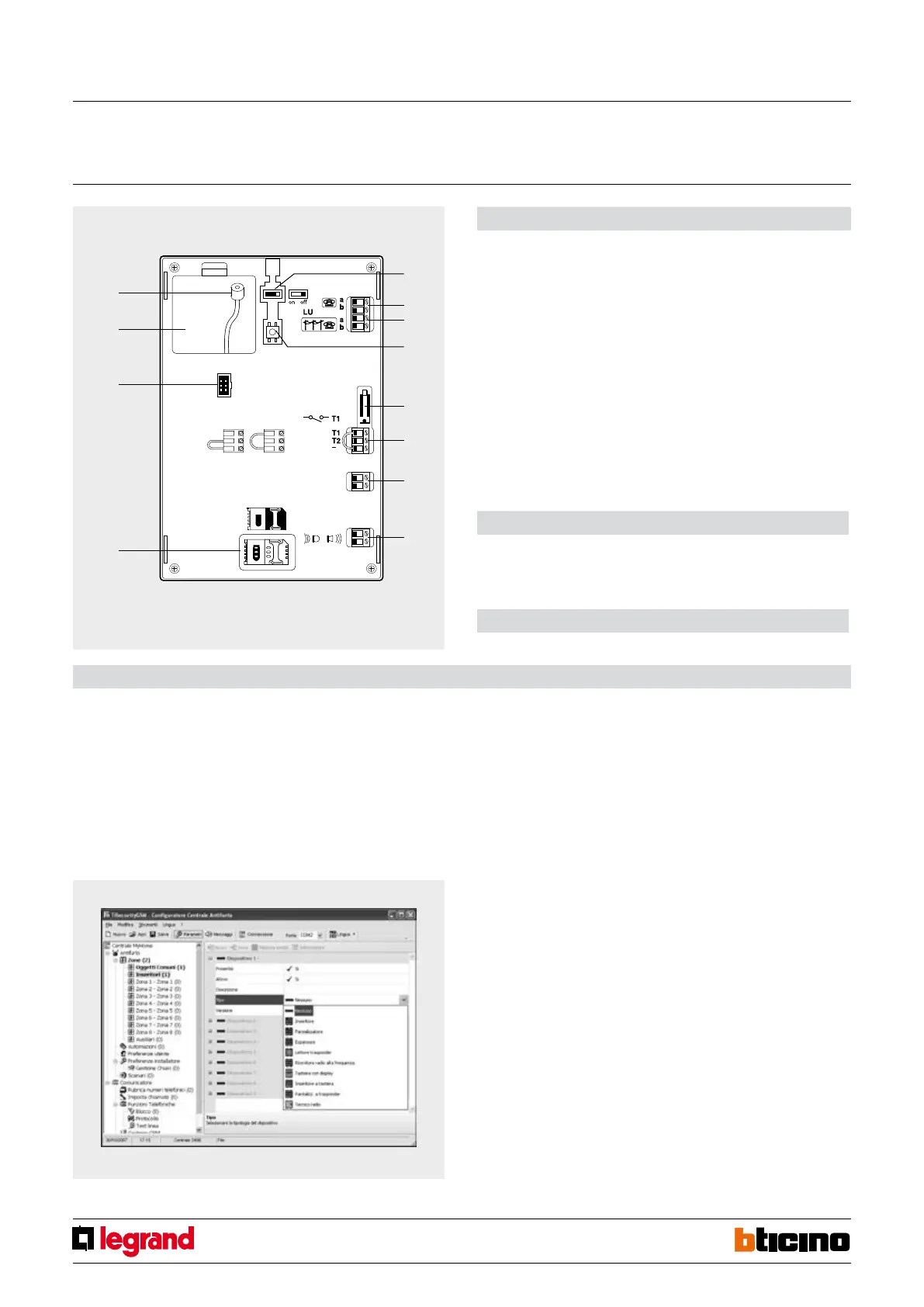
Rear view
Conguration
The central units do not need congurators. The functions can be set directly on the
device itself (keypad and display), or using the appropriate software, either TiSecurity
GSM. For detailed information refer to the corresponding manuals supplied with the
products.
Software conguration
The program can be used to easily customise all parameters of the Central unit. It is
possible to receive the current conguration from the Central unit, change it and send
any changes made to the Central unit, save the conguration to a le for subsequent
modication, or save it as a backup copy.
For further information refer to the software manual supplied with the central unit.
Ademco Contact ID functionality
Ademco contact ID is a particular communication protocol operating on a telephone line
with DTMF touch tone. Using this protocol, it is possible to set a one-way communication
between the burglar-alarm central units and the vigilance bodies. In this way, vigilance
bodies can receive information concerning the type of event/alarm generated and, if
available, the details of the peripheral from where it generated.
Events that can be managed using the Ademco Contact ID
The Ademco Contact ID events managed by the central unit are the following:
Relating to the burglar-alarm system:
- Anti-panic alarm
- Anti-burglary alarm
- General intrusion alarm
- Tamptest (device interconnection alarm)
- Device tampering alarm
- No power supply
- System battery faulty
- Activation / deactivation / cancellation*
- Sensor deactivation
- Periodical functionality test (routine check of the telephone line and the installation)
NOTE
*: cancellation is the silencing of an alarm following the disarming of the system itself.
In this case the event is sent to the vigilance body, which can therefore check if it’s been
caused by a tampering attempt.
Relating to the technical alarms:
- Fire alarm (AUX=8)
- Gas leak alarm (AUX=1)
- Freezer alarm (AUX=2)
- Flooding alarm (AUX=3)
- Remote assistance alarm (AUX=9)
- Auxiliary device tampering (Z=9)
For every event, where required, the origin of the alarm is also forwarded, in terms of zone
and device.
Technical data
- Power supply from SCS BUS: 27 Vdc
- Max. absorption: 50 (stand by) – 120 mA
- Operating temperature: 5 – 40°C
- Installation: wall mounted or Multibox switchboard
Dimensional data
Size (H,L,D): 210x210x30 mm
Legend
1 - ON/OFF slide switch;
2 - Telephone line OUT;
3 - Telephone line IN;
4 - Reset key;
5 - T1 local tamper;
6 - Tamper line (see note);
7 - Burglar alarm BUS;
8 - MY HOME sound system BUS;
9 - SIM card housing;
10 - S
erial connector for PC programming (with cable item 335919 or item 3559);
11 - Battery housing (item 3507/6);
12 - GSM antenna connector.
NOTE: The central unit is supplied with the clamps (-/T1) of the Tamper line shorted for
the use of the local tamper T1 (wall mounted installation on metal base); For installations
inside MULTIBOX boxes ensure the connection of a NC circuit breaker to the -/T1 clamps for
the tamper function; alternatively, short clamps -/T2. In this case the central unit will not be
protected from tampering.
Advanced central unit
with telephone communicator
MQ00021-c-EN 24/04/2014


 To Next Page