483
OUT
I N
C
I1 =
–
I2 =
–
I3 = 3
I4 = 2
MOD
= 1
OUT
I N
C
I1 =
–
I2 =
–
I3 = 7
I4 = 7
MOD
= 1
OUT
I N
C
I1
= –
I2
= –
I3
=
5
I4
=
4
MOD =
1
OUT
IN
OUT
IN
OUT
IN
F422
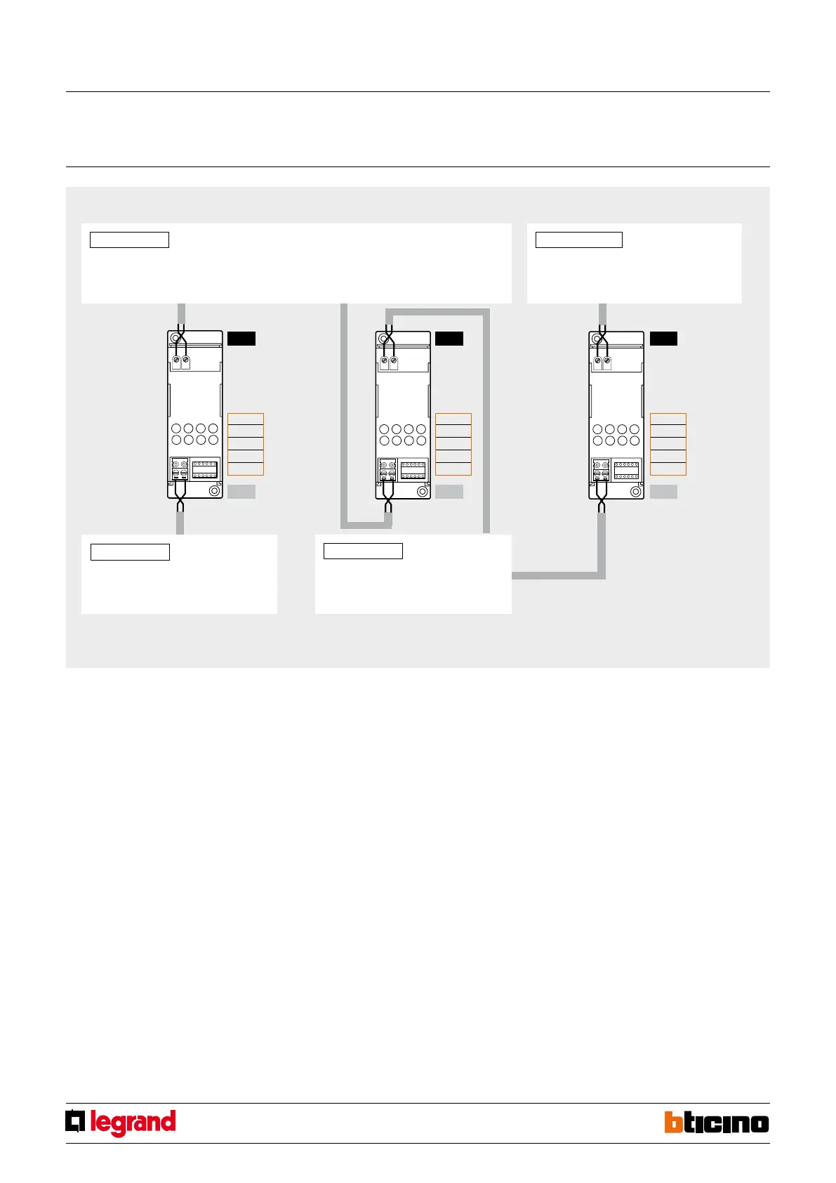
Installation example
Installation rules:
- Configure both I3 and I4 with configurators from 1 to 9, to set the separation between
the two Buses.
- I1 and I2 must not be configured.
- If several interfaces are installed in series, the addresses of the devices between one in-
terface and the other must be within those of the two interfaces (see system example).
- In this mode, it is not possible to install two interfaces in parallel on the same BUS.
- It is possible to install up to four interfaces in series, which subdivide the system in 5
separate sections, individually powered.
- The scenario module, the memory module, the IR emitter for the control of air con-
ditioning units, and the devices that can be configured in self-learning mode, must
be installed on the BUS section corresponding to the own local address (e.g. if the
scenario module is configured as A=0/PL=1, it will have to be placed on system
no. 1 - see system example).
- The web server and the scenario programmer must be installed on the BUS line with the
lowest addresses (system 1 on the drawing).
- All control devices configured for sending Point-Point, Room, Group, and General con-
trols may be connected to any branch of the system (no.1 or no. 2), without limitation,
irrespective of their respective addresses in the A and PL positions.
- The above also applies to actuators configured in “slave” operating mode.
- Interface F422 allows Point-Point, Group, Room, and General controls to travel through
the various systems. It is therefore possible to install, for example, in system no. 2 a
control configured as A=1 and PL=5 that will control actuator A=1 and PL=5 installed
in system no. 1.
- Within the system, no device must be configured with the same address as the interface.
1
3
A/PL = 55 76
Automation
2 4
A/PL = 33 53 A/PL = 78 175 (*)
Automation Automation
A/PL = 01 31
Automation
Note (*): maximum number of addresses available with virtual configuration of the devices.
1
MQ00280-e-EN 07/06/2014
SCS/SCS
gateway
 Loading...


