485
ON
ON
OFF
OUT
IN
ON
ON
OFF
OUT
IN
ON
ON
OFF
OUT
IN
287
,1
&
OUT
IN
I1 =
–
I2 =
–
I3 =
I4 =
MOD
= 3
*
*
ON
ON
OFF
OUT
IN
ON
ON
OFF
OUT
IN
ON
ON
OFF
OUT
IN
287
,1
&
OUT
IN
I1 =
–
I2 =
–
I3 =
I4 =
MOD
= 3
*
*
F422
This mode is indicated when display of burglar alarms and technical alarms are required,
generated within the common sections, using a switchboard, item 346310, installed on
the backbone or the riser of the video door entry system.
Installation rules:
• Onthecommonsectionsitispossibletoconnectcontactinterfaces,ortechnicalalarms
(gas/water leak), up to a total of 9 auxiliary channels; these must be connected to the
IN clamp of interface item F422.
(
*
) Use a free address of the video handset.
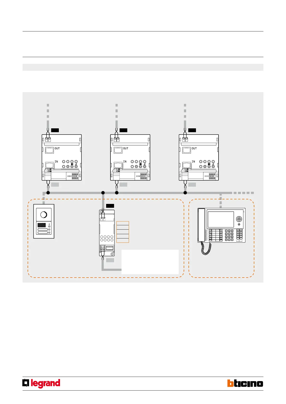
3) “Public riser” operating mode - configurator MOD = 3
Simple diagram for the display of alarms on common parts
Riser 1 Riser 2 Riser 3
Common system section
For the electric diagram see the switchboard
technical sheet.
Burglar Alarm System
(contact interfaces, gas/
water sensors, etc.)
MQ00280-e-EN 07/06/2014
SCS/SCS
gateway
 Loading...


