487
OUT
I N
C
OUT
I N
C
I1 =
–
I2 =
–
I3 =
–
I4 = 1
MOD
=
6
I1 =
–
I2 =
–
I3 =
–
I4 = 2
MOD
=
6
OUT
IN
OUT
IN
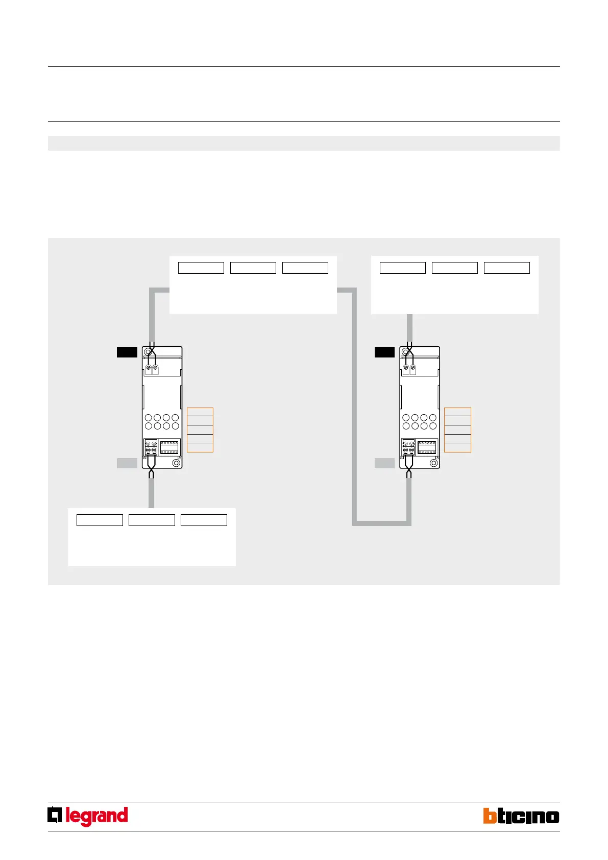
F422
This mode brings together the features of the “physical expansion” mode and the “gal-
vanic separation” mode.
Each system may be connected to both the OUT and the IN clamps of the interface and,
differently from what is required for “physical expansion” MOD=1, the addresses of the
devices of the two systems may be selected freely.
In view of the above, it will no longer be necessary to indicate the system separation
address in positions I3 and I4; therefore, the interface will have to be configured by as-
signing any address from 01 to 99, including any address already used by actuator de-
vices installed in the connected systems. If several interfaces are used, these must have
different addresses.
6) “Physical separation” mode - configurator MOD=6
Automation
System No. 2
A/PL = 15 A/PL = 26 A/PL = 48
Automation
System No. 1
A/PL = 11 A/PL = 35 A/PL = 62
Automation
System No. 3
A/PL = 27 A/PL = 35 A/PL = 78
MQ00280-e-EN 07/06/2014
SCS/SCS
gateway
 Loading...


