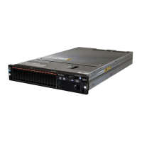
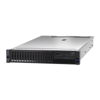
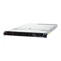
Figure111.Slot2andSlot1
Note:ThesupportedPCIslotfortheRAIDlinkfunctionisslot2and3.However,pleasenotewheninstalling
RAIDcontrollerM5120,itcanonlybeinstalledinslot1and2.
ToinstallaServeRAIDadapteronthePCIriser-cardassembly,completethefollowingsteps:
Step1.Readthesafetyinformationthatbeginsonpage“Safety”onpagevand“Installationguidelines”
onpage30.
Step2.Turnofftheserver(see“Turningofftheserver”onpage19)andallattachedperipheraldevices.
Disconnectallpowercords;then,disconnectallexternalcablesfromtheserver.
Step3.Removetheservertopcover(see“Removingtheservertopcover”onpage247).
Step4.IfyouareinstallinganeworreplacementServeRAIDadapter,touchthestatic-protectivepackage
thatcontainsthenewServeRAIDadaptertoanyunpaintedmetalsurfaceontheserver.Then,
removetheServeRAIDadapterfromthepackage.
Step5.IfyouareinstallinganeworreplacementServeRAIDadapterthatusesabattery,completethe
followingsteps:
1.RemovethebatteryfromtheServeRAIDadapterpackageorthebatterypackage.
2.InstallthebatteryandconnectthebatterytotheServeRAIDcontrollerasinstructedinthe
documentationthatcomeswiththeServeRAIDcontrollerorthebattery,orsee“Installinga
ServeRAIDadapterbatteryorflashpowermoduleintheremotebatterytray”onpage50
.
Step6.ThefollowingillustratesthestepsforinstallingaServeRAIDadapteronthePCIriser-card
assemblies:
•ForPCIriser-cardassembly1:
1.Rotatetheretentionlatchtotheopenposition.InserttheServeRAIDadapterintothePCI
riser-cardassembly,aligningtheedgeconnectorontheadapterwiththeconnectoronthe
PCIriser-cardassembly.PresstheedgeoftheconnectorfirmlyintothePCIriser-card
assembly.MakesurethattheadaptersnapsintothePCIriser-cardassemblysecurely.
2.Rotatetheretentionlatchtothecloseposition.Makesuretheretentionlatchengages
theadaptersecurely.
Chapter6.Removingandreplacingcomponents183

 Loading...


