Technical data
Leuze electronic RSL 430 107
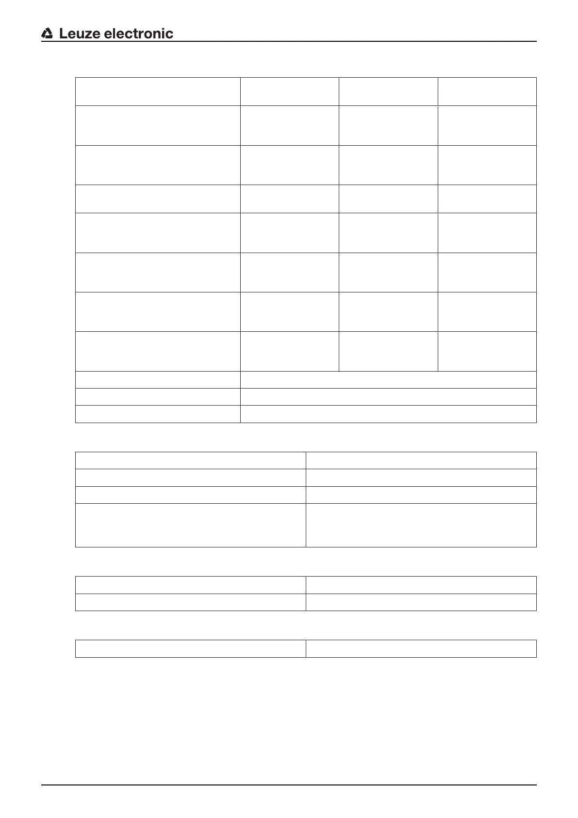
Tab.15.10: Inputs and outputs
Properties Max. output current I
a
Min. input current I
e
Typical connection
components
E=Input
(F1-F10) PNP/NPN, can be changed
over together
--- 4mA
(-4mA)
Switching contacts
control/sensor output
E=Input
(RES1, RES2) PNP/NPN
changeover together with F1-F10
--- 10mA
(-20mA)
Start/restart
E=Input
(SE1/SE2) changeover
--- 4mA
(<1mA=OFF)
E-Stop input
OSSD linkage
EX/A=changeover-capable
(EA1, EA2)
20mA
(-20mA)
10mA
(-10mA)
Auxiliary contact of
power contactor
(EDM)
E/A=changeover-capable
(EA3, EA4)
20mA
(-20mA)
4mA
(-4mA)
Switching contacts
Sensor output
Control output
A=output
Current-limited, short-circuit proof
(A3, A4)
20mA
(-20mA)
--- Control input
AX=output
Current-limited, short-circuit proof
(A1, A2, MELD)
100mA
(-20mA)
--- Lamp (PNP only)
Control input (PNP/
NPN)
Signal definition:
High/logical 1 16-30V
Low/logical 0 <3V
Tab.15.11: USB
Type of interface USB2.0
Connection type USB2.0 mini-B socket
Transmission rate ≤12Mbit/s
Cable length ≤5m
Longer cable lengths are possible using active ca-
bles.
Tab.15.12: Bluetooth
Frequency band 2400...2483.5MHz
Radiated transmitting power Max. 4.5dBm (2.82mW), class2
Tab.15.13: Software
Configuration and diagnostics software Sensor Studio for Windows7 and Windows8.1