Installation30
The 5-kVA to 10-kVA models ship with a removable power-distribution box (POD) installed, see Terminal-block
Connections on page 33, to make the electrical connections to the UPS. For removal, see the appropriate
procedures in Maintenance on page 81.
For 16-kVA to 20-kVA models, the POD ships separately and must be attached to the rear of the UPS. See
Removable Power Distribution Box on page 12, for the POD options compatible with your GXT5 model.
• Do not operate the UPS with the POD removed. To shut o all power to the POD and to the load, utility
input power must be disconnected.
To attach the POD on 16-kVA to 20-kVA units:
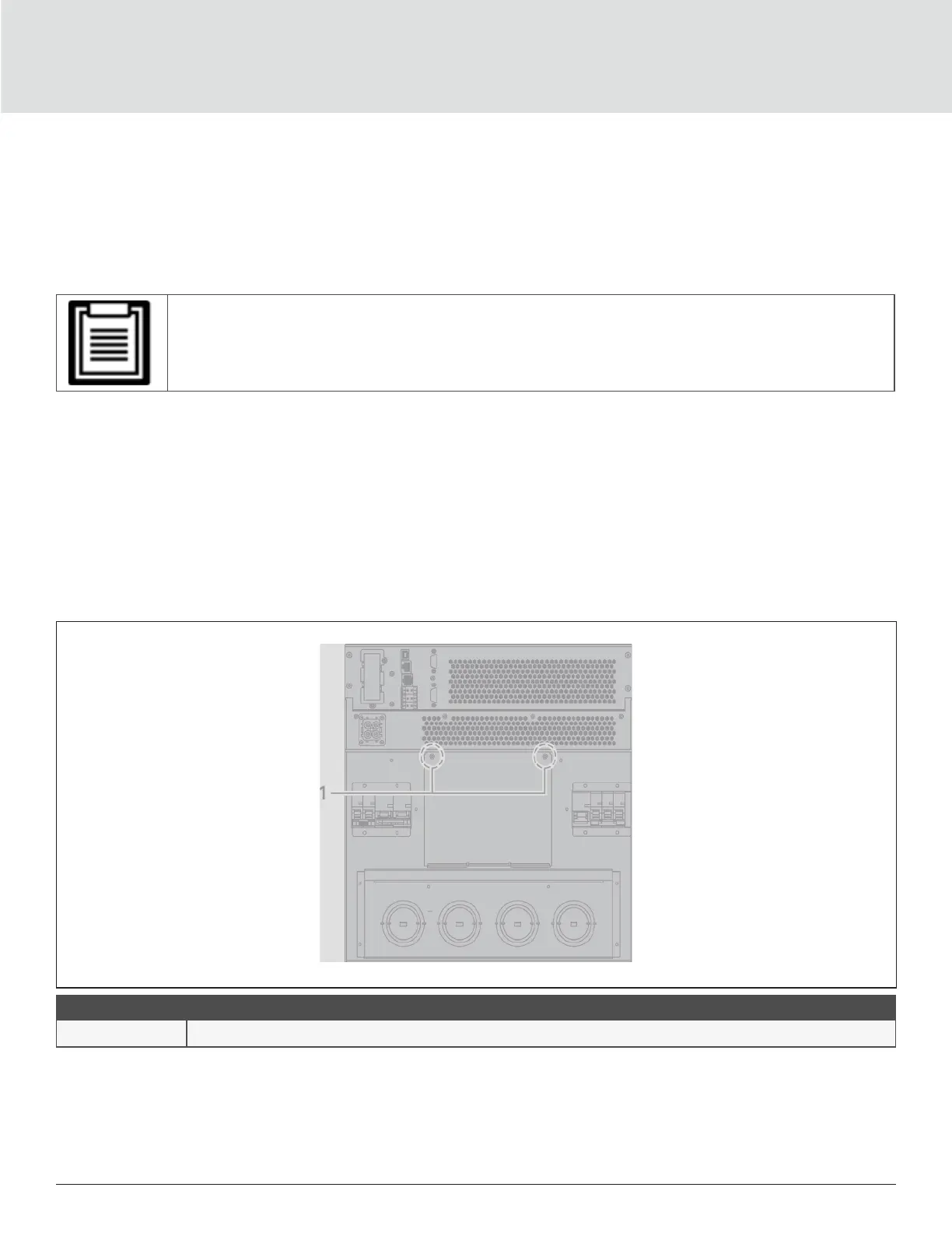
1. On the rear of the unit, unscrew the two xing screws from the POD-location cover, see Figure 2-4, and
remove the cover.
2. Insert the POD receptacles into the ports, and connect the PP75 terminal.
3. Align the POD with the installation hole, then insert and secure the POD.
Figure 2-4 POD-location cover on 16-kVA to 20-kVA models
ITEM DESCRIPTION
1 Fixing Screws