Page 228 of 295
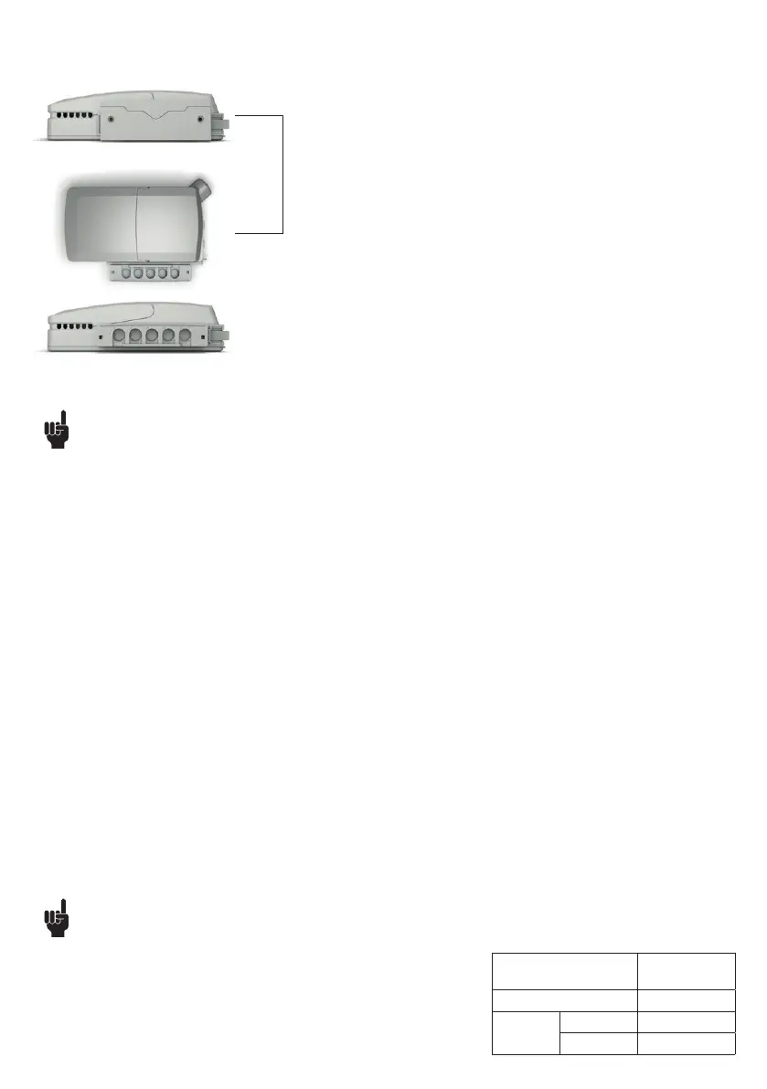
MJB5 Plus with bracket mounted on the back.
MJB5 Plus mounted on the side of the control box.
MJB5 Plus with bracket mounted on the side.
MJB5 Plus mounted on the side of the control box.
The MJB5 Plus bracket is for mounting on the CO and CB OpenBus control boxes.
Mounting examples
Recommendations
• The MJB must be mounted on an even surface
• The locking surface must be free of other material
• Always use locking mechanism and O-ring
• Sockets not used must be fitted with blind plugs to ensure the IP degree
• HOT PLUGGING
Removing or adding any OpenBus cables are not allowed when the control box is powered by mains supply!
If needed anyway follow the below procedure:
1. Remove mains and wait 5 sec.
2. Mount or dismount the required cables
If this procedure is NOT followed it may result in a damaged OpenBus driver circuit.
The risk of a damaged circuit increases if the accessory has a high start current (in rush current).
• When using USB cable (0834000) or modular plug cable (0964399) with open end, it is up to the customer to maintain the IP degree.
• Do not use 2 MJB5 Plus variants with same device ID on the OpenBus™.
This will cause conflicts and the SDT is not able to identify the different products attached.
• Before the final functional test in the production, is it important that the system is re-powered. This is to make sure that all items have been
detected on the OpenBus.
• We recommend that the end user makes a regular test procedure, in order to prevent failures and hazardous situations on the system, e.g.
squeezed cables. The MJB5 Plus is not able to detect defective 3
rd
party products.
• LINAK only takes responsibility for LINAK products, not 3
rd
party products.
Please pay attention to the “Patient Environment” Clause 3.79 - IEC60601-1.
• There can be a risk of conflict with other OpenBus accessories, such as HB, etc. it is therefore recommended to make a system/bit overview.
• When connecting 3
rd
party products to LINAK systems, the customer must take necessary precautions against Electrostatic Discharge (ESD).
Exposure to harmful ESD must be avoided.
• 3
rd
party products must be designed with the following isolation:
Minimum 1 MOPP (creepage distance/clearance according to IEC 60601-1).
• Ensure that a screw torque of 1.0 Nm is not exceeded when mounting the MJB5 Plus with or without the bracket.
MJB5 Plus SMPS Special Recommendations
• The USB cable 0834000 is not medically approved.
• The MJB5 Plus with SMPS is as standard defined as a 150 mA (4W ver.) type. This means
that when the SMPS is delivering max. power on port 2, the remaining power on the V
permanent 40V, is maximum 50 mA. This can have influence when other accessories are
connected to the system.
• When the SMPS is being used on a system with battery, the output power will follow the
power-down mode of the control box, see table
OpenBus control box
power mode
SMPS 4W
output power
On mains 4W
On battery Power down No power
“Wake up” 2W