Page 62 of 295
Hall potentiometer
Input/output specifications: absolute positioning
Item Specification Comment
Description The actuator can be equipped with an elec-
tronic circuit that gives an analog feedback
signal when the actuator moves.
Input voltage VCC = 12 - 25 VDC Feedback circuit to be powered 1 second before motor runs, and
until 1 second after the motor has stopped.
Cable dimension: 2 x AWG18 and 4 x AWG26
Output voltage POT OUT
0 - 5V
0 - 10V
0V = Fully retracted
10V = Fully extended
+/- 0.5V @ Load > 100KΩ
Current consumption Current consumption is max.40 mA. Also when actuator is not running
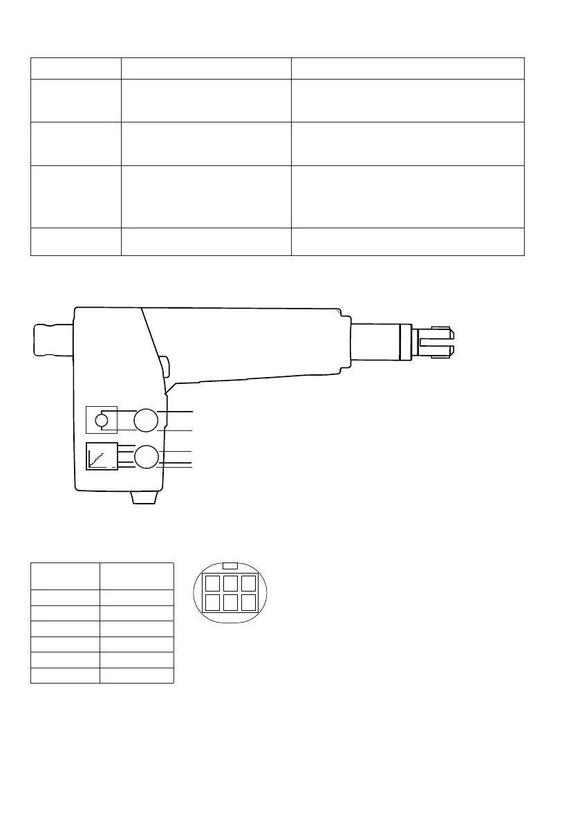
Connection diagram:
M
SIGNAL
+
Mini-Fit
Connector
Definitions
Pin 1 N / A
Pin 2 VCC
Pin 3 M +
Pin 4 POT-OUT
Pin 5 GND
Pin 6 M -
Connector front
view
654
321
PCBA Header top
view
456
123
Cable connections: