Page 89 of 295
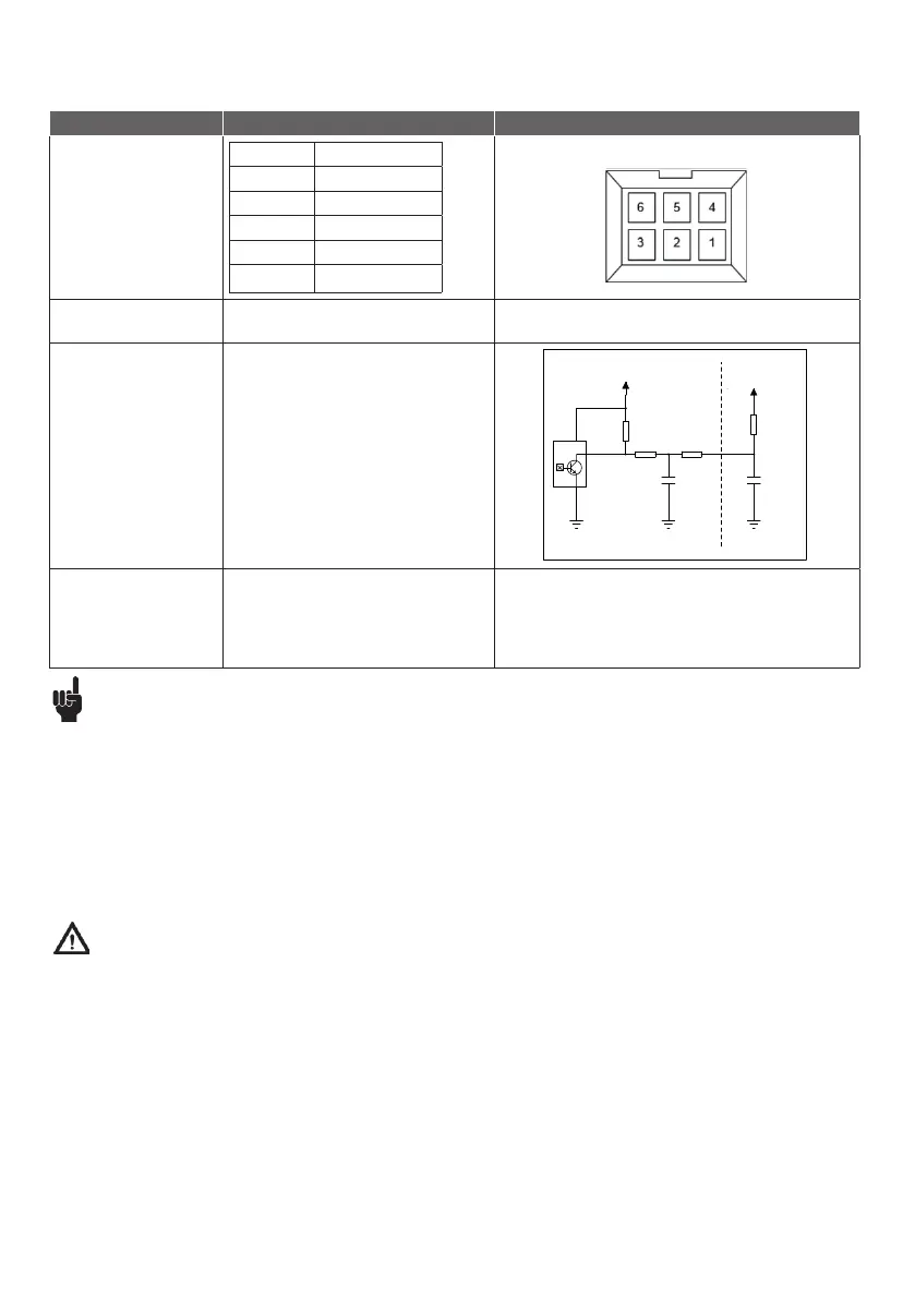
Input/output specifications: dual Hall positioning
Dual Hall digital (F3) with power switch
Item Specification Comment
Pin
configuration
Pin 1 GND
Pin 2 VCC
Pin 3 M+
Pin 4 HALL A
Pin 5 HALL B
Pin 6 M-
Connector in LC1 housing
VCC 4-15V
Current Maximum 15 mA @ 10 kΩ and 1 nF load.
See diagram.
Resolution Number of dual Hall state shifts/spindle turn:
N = 108 state/turn:
6 mm spindle: 12/108
10 mm spindle: 20/108
s
DRAWING NO:
LTR
CODE:
SIZE:
C
B
A
C
D
6 5 4 3 2 1
DATE:
D
B
A
TITLE:
COMP ANY :
RELEASED:
DATED:
DATED:
QUALITY CONTROL:
CHECKED:
DATED:
DATED:
DRAWN:
ECO NO:
APPROVED:
REVISION RECORD
SHEET: OF
SCALE :
LINAK A/S
LAxx / LCxx
Dual-Hall feedback
HALL OUTPUT
EXT. LOAD
100R
100 nF
100R
10K 1%
PWR
GND
10K 1%
1nF
VCC
VCC
Recommendations
Warnings
• Always follow the important LC1 mounting guidelines and LINAK specifications to ensure correct functionality.
• LC1 is for use in push applications, cable outlet from (smallest profile) top plate. See top plate dimensions.
• Always use LINAK compatible components and ensure that the application functionality is tested with all accessories connected
before bringing it into service.
• The mounting plate in the application must cover the entire LC1 top plate and be strong enough to carry the load.
• Regular cleaning is recommended to reduce bacteria and increase the hygiene level. Do not use chemicals for cleaning.
• The LC1 is intended for indoor use and NOT for use in harsh environments, like for instance pool or marine environments
and agriculture buildings with ammonia vapors.
• Assure free space for movement of application in both directions to avoid blockade.
• Do not expose the column to high intensity ultraviolet radiation disinfection lamps as this may damage supporting parts and cables.
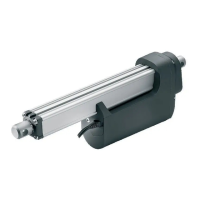
• The LC1 is heavy and weighs 9.0 kg. To avoid personal injury, DO NOT DROP!
• Always use cable lock to ensure fixation of cables and take care that the cable cannot be squeezed, pulled or subjected to any other stress or damage.
• Make a proper cable installation and inspect regularly for wear, damage and jarring sound to avoid cable interruption and actuator defects.
Defective parts must be replaced.
• A damaged housing can cause moisture to gather and lead to dangerous electrical connections between metal parts and wires.
• Always check correct assembly after mounting and service to ensure that the cable locks are mounted.
• Take special precaution concerning third party interfacing. Please contact LINAK for further information.
• Do not exceed the max. pull load specified on the label.
• Do not add dynamic load when changing between pull and push.
• Do not adjust anything during movement or while connected to mains as this may cause personal injury.
• Interconnecting cables must remain plugged in during cleaning to prevent the ingress of water.
• Mount with bottom plate downwards to obtain IPX4.
• After service inspection, the application must be tested for correct functionality before it is brought into operation to avoid misalignment
between two columns moving in parallel.
• LINAK recommends to make regular measurements of Class 1 protective ground conductivity in the application to avoid a disconnected
grounding cable. If there are worn-out or defective parts, the complete LC1 column must be replaced.