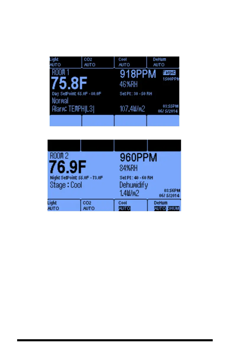
The names of the equipment being controlled, and their current control status are
displayed at the top of Room 1 screen and the bottom of the Room 2 screen. All of
the numerical values shown below are samples only and will differ for each user.
Room 1 Main Screen with Day Setpoints
Room 2 Main Screen with Night Setpoints
Temperature – Each room has its own temperature sensor with its value
displayed to one decimal point. (Fahrenheit or Celsius are selectable options)
CO
2
– Carbon dioxide levels are measured in parts per million (ppm) in each
room.
Humidity – Relative humidity is displayed for each room as a percentage.
Setpoint – If the controller is in Daytime mode, it will display Day cooling and
heating setpoints. Similarly, if the controller is in Night mode, it will display both
the night heat and night cool setpoints.
Current Temperature and or Humidity Stage – The real-time temperature
stage will be displayed below the temperature display. It will be either Normal,
Heat 1 or 2, or Cool 1 thru 6, depending on number of stages you assign. If the
controller is in humidify or dehumidify state, this real-time condition will be
displayed below the relative humidity reading.
Soft Buttons – The buttons at the top and bottom of the screen correspond to the
equipment being controlled. Below the name of the equipment is the current status