Gocator Line Profile Sensors: User Manual
Getting Started • 33
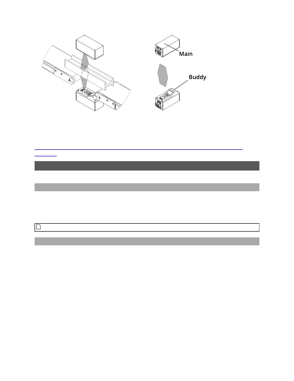
Above/below for two-sided measurement (Opposite) Main must be on the top
with Buddy on the bottom (Opposite)
For more information on setting up a dual-sensor system, see
http://lmi3d.com/sites/default/files/APPNOTE_Gocator_2300_Gocator_4.x_Dual_Sensor_Setup_
Guide.pdf.
Grounding
Components of a Gocator system should be properly grounded.
Gocator
Gocators should be grounded to the earth/chassis through their housings and through the grounding
shield of the Power I/O cordset. Gocator sensors have been designed to provide adequate grounding
through the use of M5 x 0.8 pitch mounting screws. Always check grounding with a multi-meter to
ensure electrical continuity between the mounting frame and the Gocator's connectors.
The frame or electrical cabinet that the Gocator is mounted to must be connected to earth ground.
Recommended Practices for Cordsets
If you need to minimize interference with other equipment, you can ground the Power & Ethernet or the
Power & Ethernet to Master cordset (depending on which cordset you are using) by terminating the
shield of the cordset before the split. The most effective grounding method is to use a 360-degree
clamp.
 Loading...