Gocator Line Profile Sensors: User Manual
How Gocator Works • 54
Profile Output
Gocator represents a profile as a series of ranges, with each range representing the distance from the
origin. Each range contains a height (on the Z axis) and a position (on the X axis) in the sensor's field of
view.
Coordinate Systems
Range data is reported in one of three coordinate systems, which generally depends on the alignment
state of the sensor. Sensor coordinates are used for unaligned sensors, whereas system coordinates are
used for aligned sensors. Part data can optionally be reported using a coordinate system relative to the
part itself. These systems are described below.
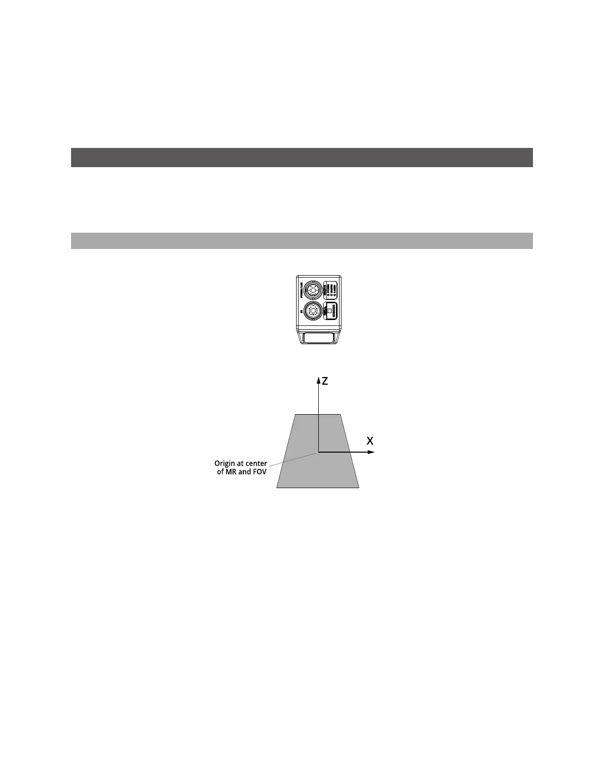
Sensor Coordinates
Unaligned sensors use the coordinate system shown below.
The measurement range (MR) is along the Z axis. Values increase toward the sensor. The sensor’s field of
view (FOV) is along the X axis. The origin is at the center of the MR and FOV.
In Surface data, the Y axis represents the relative position of the part in the direction of travel. Y position
increases as the object moves forward (increasing encoder position). The image below represents a left-
handed coordinate system.
 Loading...

