10
10
The GS550 System
The GS550 System
2.2
2.2
Load Cell
Load Cell
1. Install load cell bushings as supplied by
LSI
LSI.
Assembly of the load cell and adapter plates
must be configured to the pin size required by
the specific dead end or hook to which it is to be
attached. In all cases, the bushings supplied by
LSI
LSI must be used where possible to adapt the
holes in the load cell to the pins. Bushings must
be secured with the two allen screws provided,
one on each side of the load cell.
2. As required, place a washer between adapter
plate and pin head or nut on each end of the pin
that links the adapter plates to the load cell.
Additional washers should be added equally to
each end of the pin as required to inhibit
excessive lateral movement of load cell
(maximum 1/8” total movement) and adapter
plates along the pin.
3. If the dead end or hook to be connected to the
adapter plates requires a larger opening,
washers may be placed between the load cell
and the adapter plates equally on both sides of
the load cell.
4. In all cases the washers must be placed
symmetrically such that the load cell is centered
on the pins to avoid uneven loading.
5. Secure the pins with the nuts and cotter pins
provided.
6. A qualified (lift supervisor or crane inspector)
person must verify every lift assembly before
first use and periodically thereafter (one to
twelve months), including before any new,
difficult or otherwise different lift.
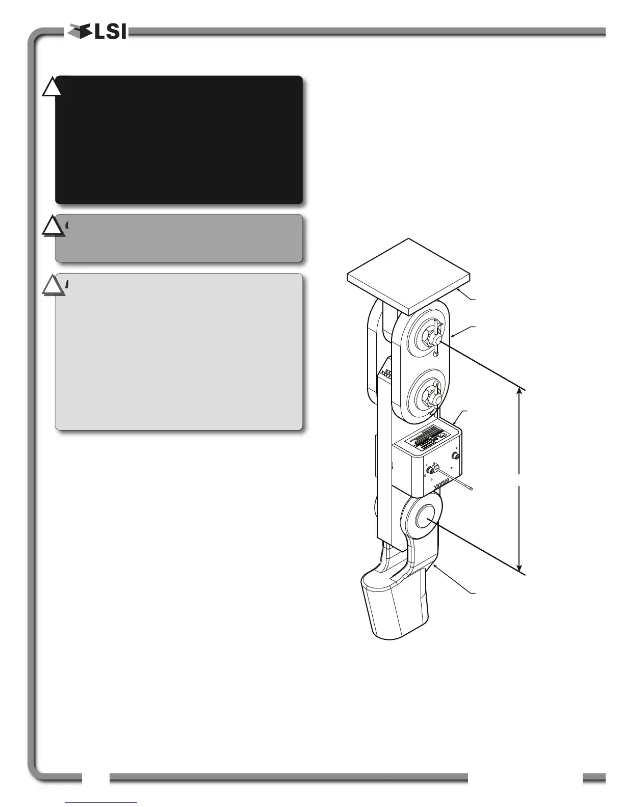
Crane dead
end
Plate kit for
loadlink
Loadcell
Wedge socket
to loaded cable
C/C
Figure: Typical load cell and adapter plate assembly installed.
IMPORTANT!
The load cell antenna should
not be in contact with metal.
IMPORTANT!
For optimal performance and
signal reception, the GS550 load cell antenna
should have a clear line of sight to the GS550
display.
IMPORTANT!
The load cell antenna should
point to the left or to the right of the boom; it
should not point directly to, or away from, the
GS550 display.
WARNING!
Capacity and safety factor for
load cells and adapter plate assemblies are
calculated for loads along the intended axis
of load (vertical with the assembly hanging
free); side loading may cause load cell and
adapter plate assembly to fail, causing load to
drop. Lifts must be rigged such that the load
cell and adapter plate assembly hang free and
not be subjected to side loading.
!
!
!
!
CAUTION!
The load cell must be centered
on the pins to avoid uneven loading on the
plate kit assembly.
!
!

 Loading...


