26
26
The GS550 System
The GS550 System
2.11
2.11
Four Point Lift
Four Point Lift
The following functions are available for applications
such as container cranes and gantry cranes that
require load indication from four load sensors
simultaneously.
• Sum load indication
• Imbalance
• Slack Rope
These functions can be used to generate an alarm
condition on the lockout wires of the GS550.
2.11a Sum Load Indication
When sum load indication is programmed the sum
of the loads on the pre-determined load sensors is
indicated by the operation display. To activate sum
load indication program a “Sum load sensor” in the
sensor list. The “ID number” is used to identify the
load sensors to be summed.
Sum maximum limit. The maximum limit for
the sum load can be adjusted in the limit menu;
the default maximum limit for sum load
indication is 10000 (lb or kg depending on load
display units).
Program sum load indication
1. Go to menu 4A1) SENSOR LIST.
2. Press Next repeatedly to advance to the next
available sensor position, usually following the
four load sensors.
3. Determine the sum load cell “ID number”. For
example: ID 1234 to indicate the sum of load
sensors № 1, № 2, № 3, and № 4, or ID 34 to
indicate the sum of load sensors № 3 and № 4.
4. Use Up and Down to adjust the ID number.
5. Press Next.
6. The sensor type should flash; use Up and
Down to select the sensor type “Sum load cell”.
7. Press Enter to save any changes.
8. Press Next to program the imbalance sensor or
press Exit three times to return to the operation
display.
9. Adjust the sum maximum limit in the limit menu.
2.11b Imbalance
Systems programmed for four load sensors and four
load sum indication can be programmed with an
imbalance sensor to warn against uneven load
distribution or against unwanted rope payout if one
corner of the load touches down before the others.
Imbalance factor limit. The imbalance factor
is the percent difference between the load on
one load sensor and the average load on the
other three. The imbalance factor is calculated
for each of the four load sensors and then
compared to an adjustable limit. The default
imbalance factor limit is 15%.
Imbalance minimum limit. Imbalance is not
calculated when the four load sum is below the
imbalance minimum limit. Adjust this limit to
avoid generating an imbalance alarm under
minimum load conditions (for example: with an
empty container or with rigging only). The
default imbalance minimum limit is 1000
(pounds or kilograms depending on load
display units).
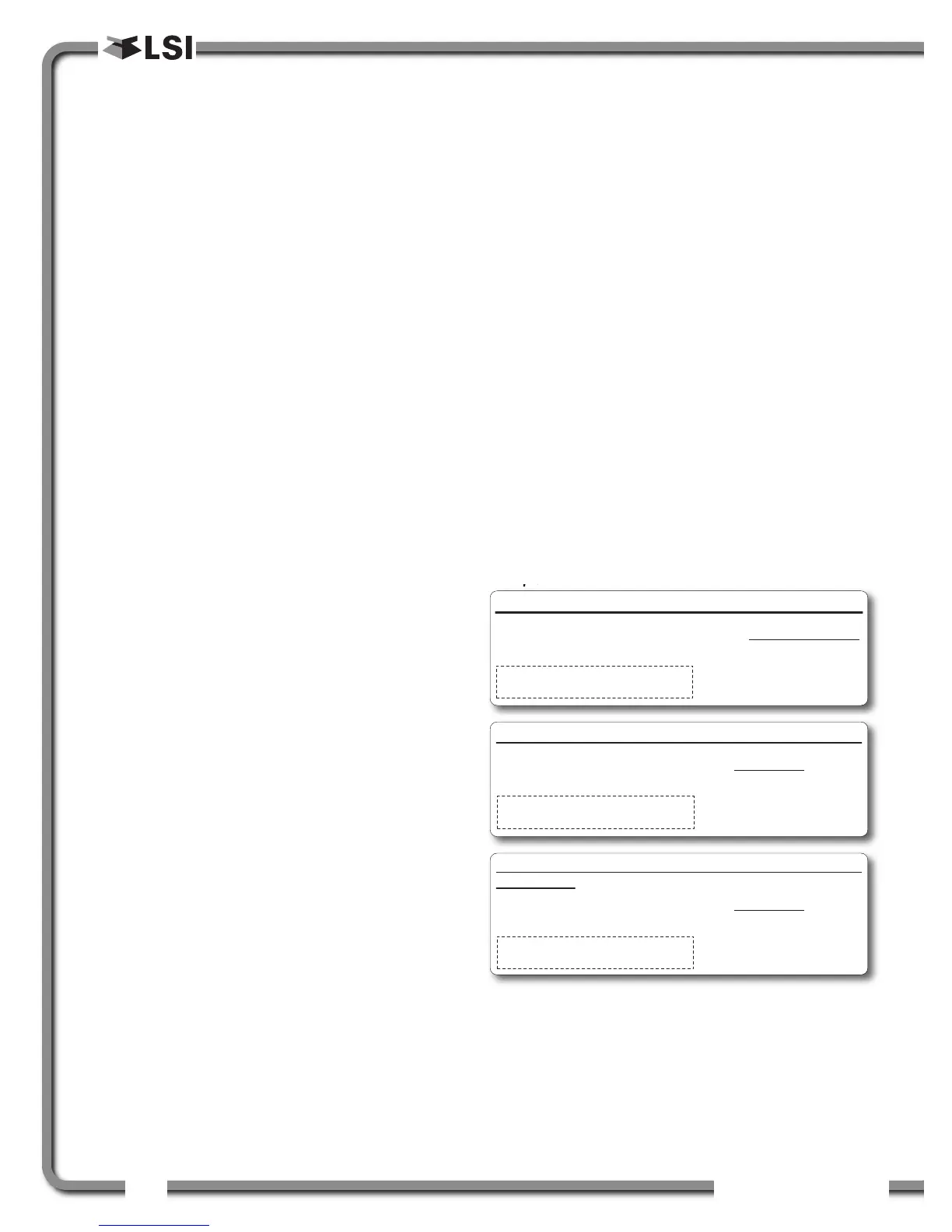
Examples:
Program the imbalance sensor
1. Go to the sensor list, menu 4A1.
2. Press Next repeatedly to advance to the next
available sensor position, usually following the
four load sensors and the sum load sensor.
3. The ID can be left at 0, press Next.
Imbalance factor calculation for load sensor № 1
A = Load № 1 B = Load № 2
C = Load № 3 D = Load № 4
Load № 1 (A) Imbalance Factor = 100 x
(Average B,C,D) - A
(Average B,C,D)
If the imbalance factor limit is 15%, then the system is safe.
A = 7500 B = 8100
C = 8000 D = 8200
Load № 1 (A) Imbalance Factor = 100 x = 7.5 %
8100 - 7500
8100
If the imbalance factor limit is 15%, then an imbalance alarm
is generated.
A = 6800 B = 8100
C = 8000 D = 8200
Load № 1 (A) Imbalance Factor = 100 x = 16 %
8100 - 6800
8100

 Loading...


