OPERATION
OPERATION
43
43
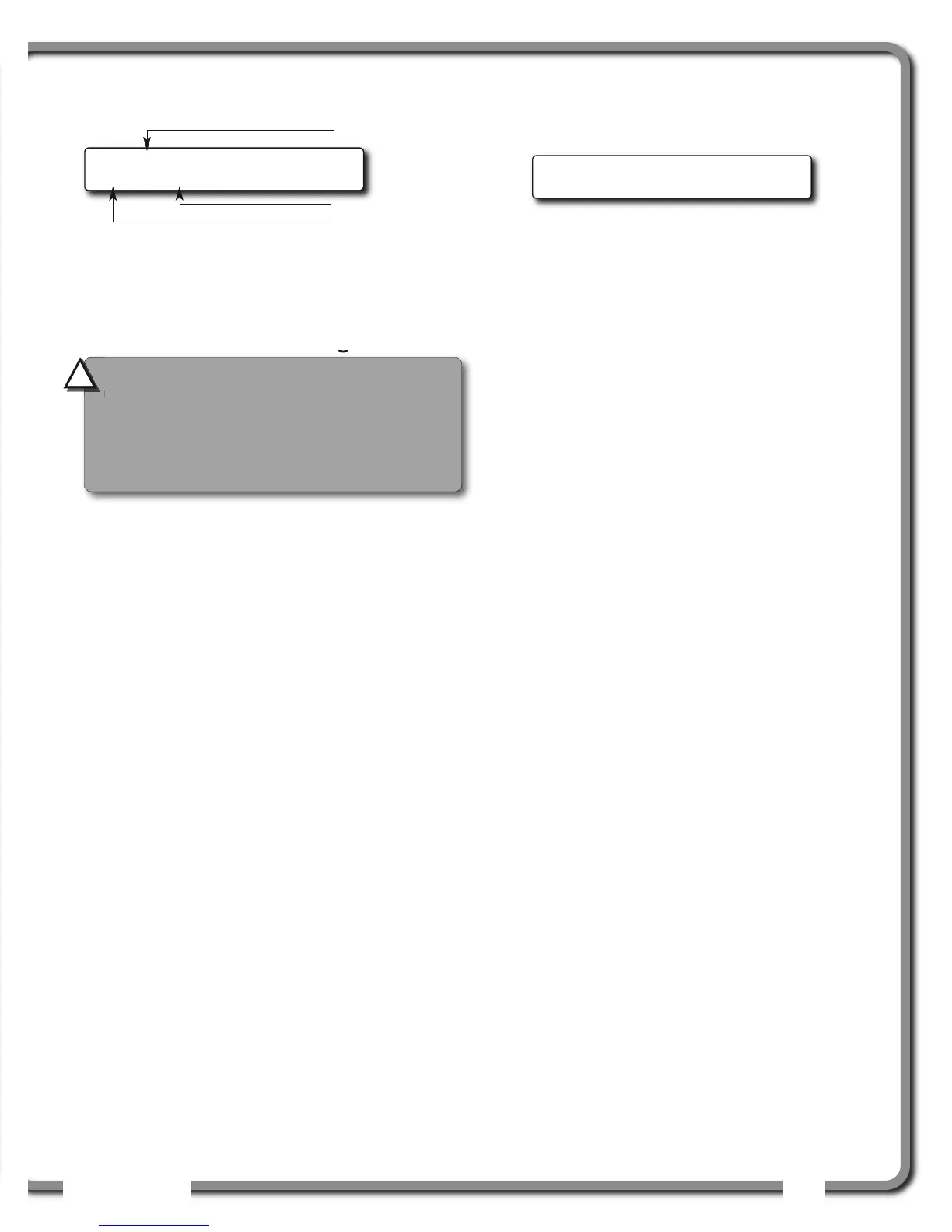
4. Press Enter to get the sensor firmware product
and version numbers.
5. Press Exit five times to return to the operation
display.
3.8b Radio Network Diagnostic
1. Go to menu 5B1) RADIO NETWORK BACKGROUND
NOISE.
2. Press Next to go to menu 5B2) LIST LAST 32
SENSORS RECEIVED.
a. Press Enter to access 5B21), THE LIST OF
THE LAST 32 SENSORS RECEIVED. Sensors are
shown with their radio ID number and the
sensor type.
b. Use Up and Down to scroll through the list.
c. Press Exit to return to menu 5B2).
3. Press Next to go to menu 5B3) SEARCH FOR
SENSORS.
a. Press Enter to launch a sensor search.
After searching, the display automatically
reverts to 5B21), the list of the last 32
sensors received (see step 2.a).
4. Press Next to go to menu 5B4) BIT ERROR RATE
COMMUNICATION TEST. This test should only be
conducted by
LSI
LSI technical service personnel.
5. Press Exit three times to return to the operation
display.
3.8c Lockout Diagnostic
Menu 5C) LOCKOUT DIAGNOSTC shows the lockout
condition of the output (alarm or safe) and the self-
test (pass or fail); it is recommended to manually
test the lockout condition;
1. Go to menu 5C1) WHITE WIRE. To temporarily
activate or desactivate the lockout relay press
Up or Down.
Figure: Menu 5C1) White Wire lockout condition example
2. Press Next to go to menu 5C2) GREEN WIRE
DIAGNOSTIC. Repeat lockout diagnostic test.
3. Press Next to go to menu 5C3) ORANGE WIRE
DIAGNOSTIC. Repeat lockout diagnostic test.
4. Press Exit three times to return to the operation
display.
3.8d Display Diagnostic
1. Go to menu 5D1) TIME AND DATE. The page
shows the current time and date according to
the GS550 internal clock.
2. Press Next to go to menu 5D2) TIME CLOCK
BATTERY. Self-test pass or fail.
3. Press Next to go to menu 5D3) EXTERNAL POWER
VOLTAGE.
4. Press Next to go to menu 5D4) DISPLAY INTERNAL
TEMPERATURE.
5. Press Next to go to menu 5D5) GS550 BASE
STATION ID. The base station ID should be the
same as the GS550 display serial number
printed on the left side of the box
6. GS550-03 portable displays only: press Next
to go to menu 5D6) BATTERY LEVEL. The battery
level of the onboard rechargeable battery pack
is indicated.
7. Press Next to go to menu 5D7) RADIO. “FCC”, “IC”
indicates Federal Communications Commission
(U.S.A.) and Industry Canada certification, “CE”
indicates European Community certification. The
frequency used by the system network is indicated
on the second line.
8. Press Exit three times to return to the operation
display.
3.8e Digital Input Diagnostic
1. Go to menu 5E4) BLUE WIRE. The page shows
the blue wire digital input status.
2. Press Exit three times to return to the operation
display.
5C1) WhiteWire: alarm
Self-test: pass
CAUTION!
The “list of last 32 sensors
received” includes all functioning GS series
sensors within range. Programming a GS550
display for sensors from a different system
will disable that system and render indication
by both systems inaccurate.
!
!
Angle sensor
B0012-2.0.0.0
Sensor type
Version number
Product number
Figure: Sensor firmware product and version numbers

 Loading...


